
Composites are becoming the material of choice for the manufacture of large, complex aerostructures. The aft section of the jumbo Airbus A380 and the wings of the military transport Airbus A400, for example, are all made of carbon-fiber composites. Boeing, for the first time, is building an all-composite airframe and wings for its groundbreaking 787 airliner. Because of these and other recent manufacturing achievements, there is little doubt that composite materials will be used extensively in many future aircraft programs — from wide-body jets and commercial airliners to regional, business, and “very light” airplanes.
Aerospace manufacturers plan to increase their use of composites because these materials offer proven benefits over aluminum and steel, such as weight reduction, improved strength, and corrosion resistance. Composites exhibit better impact response. They improve product performance, efficiency, and comfort for passengers. Composites enable part consolidation and low-cost tooling to reduce production cost and time. They also give engineers more design flexibility to customize materials based on demanding specifications, and more freedom to design unique and innovative products.
Despite the many benefits of composites, however, large aircraft structures such as wings and fuselage sections present tremendous design and manufacturing challenges. Creating a carbon fiber wing box nearly 100 feet long or a fuselage section 20 feet in diameter and 40 feet long is a complex undertaking. Aerospace engineers traditionally have used composites for relatively simple, smaller, and non-critical components. These parts were made of flat or mildly curved monolithic laminates or sandwich panels. Today, developing an entire composite fuselage from nose to tail involves the combination of multiple sets of design and structural specifications utilizing many manufacturing methods, from manual lay-up to automated fiber placement, and possibly resin infusion/injection processes for some parts.
As composite subassemblies become more complex, aerospace engineers are realizing they need to explore new, innovative design and manufacturing processes and predict part manufacturability early in development. To do so, they must more efficiently collaborate on large amounts of highly complex and interrelated data that define requirements for materials, structures, methods, and processes. This data readily affects all critical aspects of a composite part, including weight, shape, strength, cost, and producibility.
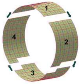
A large carbon-fiber fuselage is made up of many components such as skin panels, stringers, frames, and bonds. It is designed with numerous openings for doors and windows, local reinforcements for point loads and stress concentrations, and varying skin thicknesses that are tailored to resist aerodynamic loading, internal pressure, or bird strikes. The assembly of composite components requires accurate control of laminate thickness, ply orientation, layer boundaries, and drop-off placement so that each part meets stringent producibility requirements. In order to achieve timely design, several groups of engineers must work concurrently on all the various components. Therefore, it is critical for engineers to subsequently merge individual component designs accurately, incorporating necessary knowledge and design data in the final composite aerostructure (see Figure 1).
Each separate fuselage section or wing panel is itself a complex design. These parts involve laminate specifications for many zones of different thicknesses, and ply stacks or complex zone transition drop-offs governed by various design, structural, and manufacturing rules. For example, ply boundaries that include corner treatments known as “bird beaks” must be incorporated in the engineering model for an accurate and manufacturing ready tape laying design. Numerous details like these must be accounted for as early as possible in the design process.
One approach to designing composite aerostructures is to subdivide a large, complex part into smaller design tasks — defined either by uniform grids or by zones that present unique requirements and characteristics. Engineers then treat each grid unit or zone as an individual design task, specifying the materials and manufacturing processes peculiar to that zone. Because this methodology is efficient and promotes concurrent collaboration, it can save significant amounts of design time.

Composite parts actually are laminates made by manual or automated deposition of tens or hundreds of layers (plies or tapes) of various shapes and fiber orientations. In particular, engineers need to know the precise topology of the top and bottom surfaces, which define the final laminate. An accurate definition of these surfaces is vital for many reasons: part representation for digital mock up, part volume/ weight calculation, interference checking between mating parts, and generation of accurate tooling or manufacturing surfaces. The ability to appropriately and quickly calculate these surface specifications has been a computational challenge for design software in the past, due to the very small thickness of the plies. But the increased power and speed of computer hardware and software has given engineers the means to perform these calculations.
The manufacturing of composite structures requires careful evaluation. Most composite manufacturing methods can lead to fiber deformation, which impacts production quality and part performance. For example, hand layup of prepregs or dry materials inside a curved mold is prone to deformation such as ply wrinkling, warping, and bridging (see Figure 2), which may affect the strength, stiffness, and fatigue resistance of the final product. Fiber placement or tape laying on large fuselage panels or wing skins can produce uncontrolled deviation of fibers. Forming processes used for spars and stringers may generate stresses and strains inside and between ply layers. Unless the engineer faithfully simulates fiber deformation for all processes, the parts may not meet specifications. That failure may not be evident until physical testing, which will waste development cycles and increase costs.
Composite engineering for aerospace products has become very challenging as composite aircraft parts have increased in size and complexity, calling for new design and manufacturing methods. Specialized CAD-integrated composite engineering software is replacing manual design approaches for capturing and managing large amounts of complex and critical detailed data. Such software helps engineers automate powerful design methodologies and enables accurate virtual simulation of the as-manufactured composite structures. Specialized software will open the door to more reliable and efficient engineering of large composite aerostructures, with reduced costs, shortened development cycles, and controlled manufacturing.
This article was written by Olivier Guillermin, Director of Product and Market Strategy, for VISTAGY, Inc. For further information visit http://info.ims.ca/5787-122 .