
High-definition digital projectors based on Texas Instruments’ DLP® technology are widely known for being used in more than 90% of the world’s digital movie theaters. However, DLP chips are being selected increasingly by design engineers for use in industrial applications, including 3D printers that project violet or UV light to expose a high-resolution pattern in light-curable resin.
While 3D printing technology is rapidly revolutionizing how designers are producing prototypes and finished products, the quality and speed have not yet eclipsed traditionally molded or machined parts. This article will focus on how a team of optical and mechanical engineers were able to develop high-resolution DLP projection engines for 3D printers.
DLP Projection Engines
Objects that are produced using DLP-based 3D printers have smoother surfaces and have more complex features than those produced by selectively placing down layers of melted plastic from a nozzle, also known as FDM (Fused Deposition Modeling). Similar to the conventional laser stereolithography method, DLP 3D printers require a reactive resin that must be turned into a solid through the use of some type of curing, in this case violet or near UV light.
To achieve high brightness and high resolution, the projection engine within the printer must be capable of producing a sharp, uniform projected image with sufficient energy to harden the material at a reasonable rate. Greenlight works with a 3D Printer OEM to select the most appropriate DLP chipset (also called a DMD or digital micromirror device), depending on the desired print area, activation wavelength, required resolution, and printer cost target.
The projection engine starts with one or more high-output LED arrays or large LED chips. The LEDs are configured in a rectangular pattern in order to match the étendue of the DMD chip and the optical system. A growing number of violet (405nm) and UVA (350nm-400nm) off-the-shelf LED packages are available or a custom package can be designed and manufactured. In addition to matching the size of the LED to the DMD, it is important to consider the mechanical configuration of the LED package, the output and efficiency of the LED, the thermal management of the LED package, and the ability to efficiently capture the light from the LED.
With DLP-based 3D printing, the intensity of the light has a direct correlation to the speed of print and quality of the final product. Therefore, engineers designed the optical system with a low f-number to enable a larger light source and higher energy output, while allowing the optical components to correct for aberrations that can occur at the selected aperture size.
A system with a low f-number can be challenging to design and manufacture since the DMD can only accept certain angles of light and large aperture projection optics require advanced design to control aberrations. Similarly, LEDs emit light at very large angles, requiring a significant amount of stray light correction in order to maximize the light collected. The projection engine example used for this article features output of greater than 1 watt of optical power.
Designing Turnkey Optical Systems
From the beginning of the project, this projection engine design was focused on the construction and modularity of the system so that it can be used for the DLP-based 3D printers, as well as to project structured light patterns that can be used for industrial or medical 3D scanning applications.
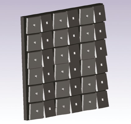
Being part of Texas Instruments’ DLP Design Network enables Greenlight’s optics designers to access the development tools and the latest DMDs to accelerate their projects. The projection engine from Greenlight Optics shown in Figure 2 includes the Texas Instruments DLP6500 featuring 2,073,600 highly reflective digitally switched 7.6μ micromirrors for a resolution of 1920 x 1080 square pixels.
However, just having access to these chips isn’t enough. Optical engineers need to understand how to apply these tools to their lens and optics designs. In today’s world where time-to-market is paramount, that means leveraging optical simulation tools to ensure products can meet performance criteria prior to manufacture.
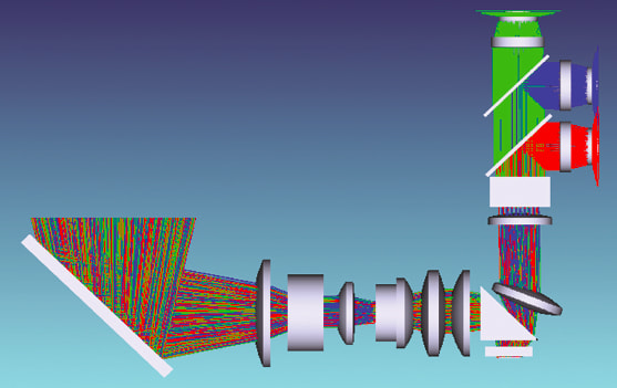
The design engineers use several software tools to model and simulate their designs. For illumination and optical engineering, TracePro from Lambda Research Corporation was used to simulate the complete system – from the LED array to the DMD and out of the projection lens. By accurately modeling the light from the source to the projection plane, the optical designer follows an iterative process to create a design simultaneously achieving high efficiency and high uniformity. This is particularly important for industrial 3D printing where layers in the resin must cure at the same rate and with small variations in layer thickness. Identifying issues that may cause a lack of uniformity are easier to resolve in a software simulation rather than trial-and-error prototyping.
The optical engineer responsible for integrating the LED array into the system had to take into account the challenges posed with that light source, such as tolerance, stray light, optics material selection, design for manufacturing, and opto-mechanical alignment and testing. This was done by modeling the optical system performance across a range of working parameters to ensure that the system will perform as required.
Using Monte-Carlo analysis and other techniques, manufacturing tolerances and environmental conditions are considered during the optical design stage to ensure that designs are manufacturable and designs will perform under real conditions. Stray light simulation helps to improve contrast and provides the mechanical engineers with critical information to complete the opto-mechanical design.
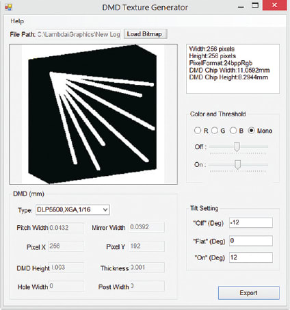
The optical designer uses TracePro to model the complete opto-mechanical system. The designer adds optical properties to all the components, and then employs TracePro’s RepTile surface property to model thousands of micro-mirrors. The Reptile algorithm in TracePro does not create actual CAD geometry, it creates the DMD surfaces on the fly when a ray intersects the base surface the DMD is based upon, eliminating the need to create enormous CAD files that significantly reduce analysis time. Surface properties are then added to both the mirror surface and the surface below the mirror array to create a more realistic representation of the DMD. To correctly set up the DMD “ON” and “Off” states, TracePro includes a DMD texture generator that loads BMP, and JPG files and correctly sets the mirrors states to generate the image loaded. Figure 3 shows the DMD texture generator menu dialog to create the TracePro logo ready for raytracing as a RepTile property.
At this point, the designer raytraces the full system with the textured DMD in place. It is now a simple matter of using the program’s “Visual Ray Sorting”, “Path Sort Table” and Irradiance Map capabilities to look for sources of ghosting and stray light in the systems. With specific “On/Off” textures set, the designer can look both visually and quantitatively for ghosts or stray light problems inherent in the design on any surface or area using these capabilities.
The “Visual Ray Sorting” capability allows the designer to visually sort rays based on absorbed, specular, and scattered criteria, as well as by flux percentage for each source in the system. The “Path Sort Table” capability creates a spreadsheet of different paths that each set of rays can take to reach the selected surface in the model tree. Each path is broken down in terms of number of surfaces intersected, power contributed, and the path taken surface by surface. This path sort table can be used in conjunction with the system model viewer to visually show the rays for each selected path and the power contributed for that path, all on screen at one time. This type of analysis gives insight to the designer to properly place baffles and optical edge shapes to minimize stray light and reduce ghosts to acceptable levels.
Prototyping and Commercialization
With the initial optical and mechanical design completed with the aid of software, it is still a critical step to prototype the projection engine prior to production. Using its in-house glass and plastic optics fabrication, mount machining, assembly and alignment, and testing capabilities, Greenlight is able to quickly build and test the prototype projection engine. Results of the prototyping are analyzed by the engineering team and an iterated production optical and mechanical design is created using the same software tools used in the prototype design.
This article was written by Michael O’Keefe, Managing Partner, Greenlight Optics (Loveland, OH) and Michael Gauvin, VP Sales & Marketing, Lambda Research (Littleton, MA). For more information, contact Mr. O’Keefe at