
An instrumentation system for direct measurement of the thermal conductivity of a small sample of a highly insulating material has been devised. As used here, (1) “small” signifies having dimensions of the order of two centimeters — significantly less than the sizes of specimens for which prior devices for direct measurement of thermal conductivity have been designed; and (2) “highly insulating” signifies having thermal conductivity of the order of that of air.
The electric power supplied to the heated disk is adjusted to maintain the temperature of this disk at a fixed value (for example, 35 °C) that exceeds the temperature in the chamber by a fixed amount. Similarly, the supply of chilled water to the cooled disk is regulated to maintain the temperature in this disk at a value (in the present example, 15 °C) below the chamber temperature by the same fixed amount. Modeling shows that the resulting symmetry in the temperature differential, in combination with the geometric symmetry of the apparatus, serves to ensure that heat escaping from the edge of the heated disk flows through the air-gap region and, for the most part, returns to the edge of the cooled disk. It also ensures that the heat escaping from the half of the guard ring that is positioned toward the heated disk flows to the half of the guard ring positioned towards the cooled disk. This helps to assure one-dimensional heat flow through the sample, thereby minimizing the measurement errors. The time-averaged heater power needed to maintain the specified constant temperature of the heated disk in the steady state is what is measured.
The following description of the theory of operation and the calculation of thermal conductivity from measurement data is somewhat simplified for the sake of brevity. The heater power is nominally given by
Q = kAΔT/l + QL,
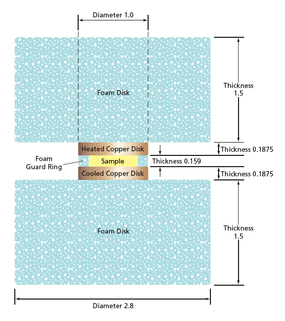
where k is the thermal conductivity of the sample material under test, A is the cross-sectional area of the sample (nominally, the area of the circle enclosed by the guard ring), ΔT is the specified difference between the temperatures of the heated and cooled disks, l is the thickness of the sample, and QL is the rate of leakage of heat along all paths other than that of direct one- dimensional thermal conduction through the thickness of the sample.
Modeling shows that the combination of temperature-differential and geometric symmetry and the one-dimensional heat flow through the sample ensures that the heat-leakage power is essentially independent of the sample material. Hence, it is possible to determine the value of QL as a function of the heated disk, cooled disk, and chamber wall temperatures from calibration measurements on one or more specimens having known thermal conductivities. Modeling also shows that the device may be calibrated using air as the reference standard material. Thereafter, one can use the value of QL as thus determined to calculate values of k from measured values of Q.
This work was done by Robert A Miller and Maria A Kuczmarski of Glenn Research Center.
Inquiries concerning rights for the commercial use of this invention should be addressed to NASA Glenn Research Center, Innovative Partnerships Office, Attn: Steve Fedor, Mail Stop 4–8, 21000 Brookpark Road, Cleveland, Ohio 44135. Refer to LEW-18356-1.