There are many different types of filters in machine vision that can be utilized to improve or change the image of the object under inspection. It is important to understand the different technologies behind the various types of filters in order to understand their advantages and limitations. Although there is a wide variety of filters, almost all can be divided into two primary categories: colored glass filters and coated filters.
Colored Glass Filters
Colored glass filters are incredibly common in machine vision, and are created by doping glass materials with elements that selectively change their absorption and transmission spectra. The dopants vary based on which wavelengths are considered for transmission, and the manufacturing process is then nearly identical to standard optical glass manufacturing.
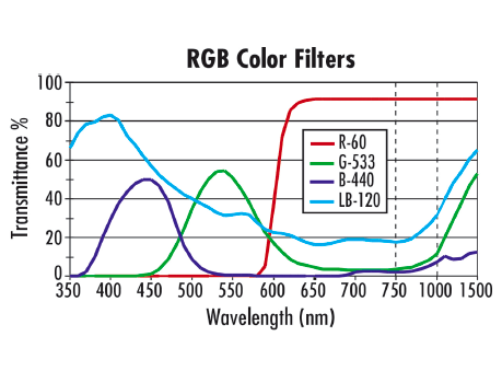
Colored glass filters are advantageous for a couple of different reasons: they are of relatively low cost when compared to interference filters and, more importantly, they do not demonstrate any shift in wavelength transmission when used with wide angle lenses or at an angle. However, colored glass filters also typically feature wide cut-on wavebands, do not have curves that are as sharp or accurate as coated interference filters, and do not have transmission throughput levels (percentages) as high as interference filters. Figure 1 shows the transmission curves for several common colored glass filters. Note that the filters feature wide cut-on wavebands and have relatively shallow slopes describing their transmission functions.
Figure 1. Transmission curves for several different colored glass filters. Infrared (IR) cutoff filters can be either colored glass filters or a type of coated filter that is useful for both monochrome and color cameras in machine vision applications. Since the silicon sensors in most machine vision cameras are responsive to wavelengths up to approximately 1 m, any IR light incident on the sensor that may have been caused by overhead fluorescent lights or other unwanted sources can create inaccuracies on the sensor. On a color camera, IR light will create a false color on the sensor that can degrade overall color reproduction. For this reason, many color imaging cameras come standard with IR-cut filter over the sensor. With monochrome cameras, the presence of IR light will degrade the contrast of the overall image.
There are a multitude of other types of colored glass filters. For instance, daylight blue filters can be used for color balancing when polychromatic light sources and color sensors are used.
Coated Interference Filters
Figure 2. Transmission curve examples of longpass and shortpass (a) and bandpass and notch filters (b). Coated filters typically offer sharper cut on and cut off transitions, higher transmissions, and better blocking than colored glass filters. In addition to colored glass filters, there are a range of coated filters, from hard coated fluorescent filters to dichroic filters to polarization filters. Each coated filter undergoes a unique manufacturing process to ensure the proper performance. Wavelength-selective optical filters are manufactured by depositing dielectric layers on a specific substrate of alternating high and low indices of refraction. The surface quality and uniformity of the substrate establishes the baseline optical quality for the filter, along with setting wavelength limits where the transmission of the substrate material falls off. The dielectric layers produce the detailed spectral structure of a filter by creating constructive and destructive interference across a range of wavelengths, as well as providing much sharper cut-off and cut-on bands when compared to colored glass filters.
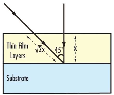
Figure 3a. Interference filters function based on the distance that light incident upon the filter travels. At the correct angle of incidence, the light waves incident on the filter destructively interfere, disallowing them from making it through the filter. At a different angle, the destructive interference is not as effective, essentially changing the type of filter. Many types of hard-coated filters exist, such as bandpass, longpass, shortpass, and notch filters, each with a specified blocking range and transmission range. Longpass filters are designed to block short wavelengths and pass long wavelengths. Shortpass filters are the opposite, passing shorter wavelengths and blocking longer. Bandpass filters pass a band of wavelengths while blocking longer and shorter wavelengths. The inverse of a bandpass filter is a notch filter, which blocks a band of wavelengths and passes the longer and shorter. Transmission curve shapes for these filter types are shown in Figure 2.
Filters designed for deep blocking (high Optical Density) and steep slopes (sharp transition from blocking to transmission) are used in applications where precise light control is critical. Most machine vision applications do not require this level of precision; typically, any filter with an Optical Density (OD) of 4 or greater is more precise than required and adds unnecessary cost.
Figure 3b. An example of blue shift, shown with a bandpass filter used at a 15° angle of incidence. Note not only the shift towards a lower center wavelength, but the shal Because hard coated filters utilize optical interference to achieve such precise transmission and rejection bands, they introduce some difficulties when used in machine vision applications. All interference filters are designed for a specific Angle of Incidence (AOI), generally 0° unless specifically defined otherwise. When used in machine vision, these filters are generally placed in front of the lens; doing so causes the filter to accept light coming from angles dictated by the angular field of view of the lens. Especially in the case of short focal length (large angular field of view) lenses, the light that is transmitted through the filter will often display an unwanted effect known as blue shift. For example, a 4.5mm focal length lens (wide angle) will have a much larger blue shift than a 50mm focal length lens (narrow angle).
As the AOI on an interference filter increases, the optical path length through the filter layers increases, which causes the cut-on and cut-off wavelengths to decrease (Figure 3). Therefore, at different field points in the image, the filter will behave differently by transmitting different wavelength ranges: the farther out in the field, the more pronounced the blue shift. In most cases, interference filters can still provide better filtering control over a colored glass filter, but be aware of the potential pitfalls when using an interference filter with a wide-angle lens.
Applications with Machine Vision Filtering
Figure 4. Color wheel demonstrating that warm colors should be used to filter out cool colors on the opposite side of the wheel. When designing a machine vision system, it is important to enhance the contrast of the inspected object’s features of interest. Filtering provides a simple way to enhance the contrast of the image while blocking out unwanted illumination. There are many different ways filters can enhance contrast, and the filter type is dependent on the application. Some common filters used in machine vision are colored glass, interference, Neutral Density (ND), and polarization.
Colored glass bandpass filters are some of the simplest filters available for drastically improving image quality. These filters work incredibly well at narrowing the waveband that is visible by the vision system, and are often less expensive than comparable interference filters. Colored glass filters work best when used to block out colors on the opposite side of the color wheel (Figure 4).
Color Filters
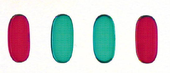
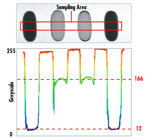
Figure 5. Four liquid capsules under inspection with the same vision system, shown here in color. Consider the example shown in Figure 5, where gel capsules are being inspected. As shown, two red capsules are on the outer sides of a pair of green capsules and under a white light backlight. This is a sorting application where the pills need to be separated by color to reach their respective locations. Imaging the capsules with a monochrome camera (Figure 6) provides a contrast between the green and red capsules of only 8.7%, which is below the minimum advisable contrast of 20%.
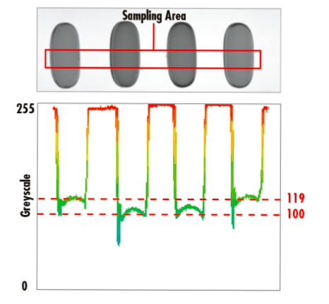
Figure 6. Capsules being viewed with a monochromatic camera, yielding a contrast of 8.7%. In this particular example, minor fluctuations in ambient light, such as individuals walking past the system, can decrease the already low contrast value of 8.7% enough so that the system is no longer capable of operating properly. Several solutions to this problem exist: a bulky and costly light baffling system can be built to completely enclose the inspection system, the entire lighting scheme of the system can be reworked, or a filter can be added to enhance the contrast between the green and red pills. In this instance, the simplest and most cost effective solution is to utilize a green colored glass filter in order to improve the contrast between the two different colored capsules. As shown in Figure 7, the contrast improves from 8.7% to 86.5%: an increase of nearly a factor of 10.
Neutral Density Filters
Figure 7. Capsules being viewed with a monochromatic camera and green colored glass filter yielding a contrast of 86.5%. Neutral density filters are used in certain applications where it is advantageous to have additional control over the brightness of an image without changing the exposure time or adjusting the f/#. Although there are two primary types of neutral density filters (absorbing and reflecting), their overall responsibility is the same: uniformly lower the light that is transmitted through the lens and onto the sensor. For applications like welding where the imager can be overloaded regardless of the exposure time, neutral density filters can provide the necessary drop in throughput without needing to change the f/# (which can impact the resolution of the system). Specialty neutral density filters, like apodizing filters, exist to help with hotspots in the center of an image caused by a harsh reflection from an object, but the optical density decreases with radial distance away from the center of the filter.
Polarizing Filters
Polarization filters are another common type of filter used in machine vision applications as they allow better imaging of specular objects. In order to properly use polarizing filters, it is important that both the light source and the lens have polarization filters on them. These filters are called the polarizer and the analyzer, respectively. Figure 8 shows an example of how polarization filters can make a difference when viewing specular objects. In the Figure 8a, a transparent object is being inspected with brightfield illumination and Figure 8b shows the same illumination setup with a polarizer on the light source and an analyzer on the lens.
Figure 8. Images of transparent objects taken without polarizer (a) and with polarizer (b) showing how stressed material becomes birefringent. As shown in Figure 8b, stress, or unwanted refractive index variations, causes a rotation in the angle of polarization. Viewing an unstressed clear object between crossed polarizers should yield a completely dark field. However, when stress is present, the localized changes in refractive index actually rotate the angle of polarization to give varying degrees of transmission - even different amounts of transmission for different colors.
It is critical to understand that filters exist to manipulate the contrast of an image in order to help increase the accuracy of the imaging system. Whether it is simple color filtering or polarization filtering, each filter exists to solve a unique problem; it is important to understand what filters should be used for specific applications.
This article was written by Gregory Hollows, Director, Imaging Business Unit, Edmund Optics (Barrington, NJ). For more information, contact Mr. Hollows at This email address is being protected from spambots. You need JavaScript enabled to view it. or visit http://info.hotims.com/61061-200 .

 Colored glass filters are incredibly common in machine vision, and are created by doping glass materials with elements that selectively change their absorption and transmission spectra. The dopants vary based on which wavelengths are considered for transmission, and the manufacturing process is then nearly identical to standard optical glass manufacturing.