
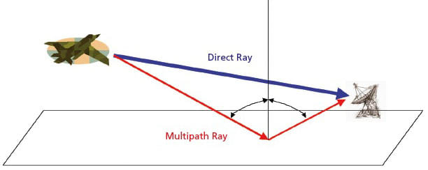
A spatio-temporal equalizer has been conceived as an improved means of suppressing multipath effects in the reception of aeronautical telemetry signals, and may be adaptable to radar and aeronautical communication applications as well. This equalizer would be an integral part of a system that would also include a seven-element planar array of receiving feed horns centered at the focal point of a paraboloidal antenna that would be nominally aimed at or near the aircraft that would be the source of the signal that one seeks to receive (see Figure 1). This spatio-temporal equalizer would consist mostly of a bank of seven adaptive finite-impulse-response (FIR) filters — one for each element in the array — and the outputs of the filters would be summed (see Figure 2). The combination of the spatial diversity of the feed-horn array and the temporal diversity of the filter bank would afford better multipath-suppression performance than is achievable by means of temporal equalization alone.
The seven-element feed array would supplant the single feed horn used in a conventional paraboloidal ground telemetry-receiving antenna. The radio-frequency telemetry signals received by the seven elements of the array would be digitized, converted to complex baseband form, and sent to the FIR filter bank, which would adapt itself in real time to enable reception of telemetry at a low bit error rate, even in the presence of multipath of the type found at many flight test ranges.
Each channel (comprising the signal-processing chain for a receiving feed horn) would contain an N-stage FIR filter. The incoming complex baseband signal in the ith channel at the nth sampling instant is denoted by yi(n). A filter weight at that instant is denoted generally by wi,j(n), where i is the index number of the channel (1 ≤ i ≤ 7) and j is the index number of the filter stage (0 ≤ j ≤N – 1). The signal-combining operation at the summation (output) point of the FIR filter bank is given by
where wi,0≡1. The weights would be adapted by an algorithm known in the art as the constant-modulus algorithm, embodied in the following equation:
wi,j(n + 1)= wi,j(n)+ αyi(n – j)z*(n)
[1 – |z(n)|2],
where α is an adaptation rate parameter.
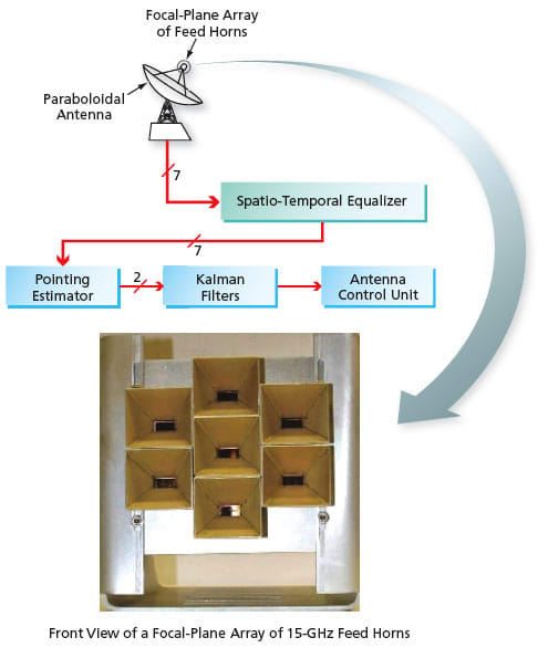
In addition, the combination of the array and the filter bank would make it possible to extract, in real time, pointing information that could be used to identify both the main beam traveling directly from the target aircraft and the beam that reaches the antenna after reflection from the ground: Information on the relative amplitudes and phases of the incoming signals, which information would be indicative of the difference between the antenna pointing direction and the actual directions of the direct and reflected beams, would be contained in the adaptive FIR weights. This information would be fed to a pointing estimator, which would generate instantaneous estimates of the difference between the antenna-pointing and target directions. The time series of these estimates would be sent to a set of Kalman filters, which would perform smoothing and prediction of the time series and extract velocity and acceleration estimates from the time series. The outputs of the Kalman filters would be sent to a unit that would control the pointing of the antenna, enabling robust pointing even in the presence of multipath.
The performances of several receiving systems with and without multipath and both with and without several conceptual versions of the spatio-temporal equalizer have been demonstrated in computational simulations. It was planned to begin construction of a breadboard version of the spatio-temporal equalizer at or about the time of writing this article.
This work was done by Ryan Mukai, Dennis Lee, and Victor Vilnrotter of Caltech for NASA’s Jet Propulsion Laboratory. For more information, download the Technical Support Package (free white paper) at www.techbriefs.com/tsp under the Electronics/Computers category.
This invention is owned by NASA, and a patent application has been filed. Inquiries concerning nonexclusive or exclusive license for its commercial development should be addressed to
the Patent Counsel
NASA Management Office–JPL.
Refer to NPO-43077.
This Brief includes a Technical Support Package (TSP).
Spatio-Temporal Equalizer for a Receiving- Antenna Feed Array
(reference NPO-43077) is currently available for download from the TSP library.
Don't have an account?
Overview
The document discusses the Spatio-Temporal Equalizer for Array Feed Equipped Parabolic Antennas, identified as NPO 43077, developed by NASA's Jet Propulsion Laboratory (JPL). This technology addresses significant challenges faced by the United States Air Force (USAF) during flight test telemetry, particularly the issues arising from time-varying frequency-selective multipath caused by ground reflections of radio-frequency (RF) telemetry signals. Such multipath effects can lead to increased bit error rates and diminished telemetry performance, which are critical concerns in flight testing scenarios.
To mitigate these issues, the proposed solution employs a spatial array of receiving horns that replaces traditional single horn feeds in parabolic ground receiving antennas. This innovative approach combines spatial diversity with temporal finite impulse response (FIR) equalization, utilizing the constant modulus algorithm (CMA) to effectively compensate for common forms of multipath interference. The system consists of a feed array with seven horns, which captures RF signals that are then converted to complex baseband. These signals are processed through a space-time adaptive FIR filter structure that dynamically adjusts to compensate for multipath effects in real-time.
The novelty of this work lies in its ability to leverage spatial diversity alongside temporal equalization, resulting in superior channel equalization performance compared to methods that rely solely on temporal techniques. This advancement enables low bit error rates and enhances the reliability of telemetry reception, even in challenging environments typical of many flight test ranges.
The document emphasizes the broader implications of this technology, suggesting that the developments in spatio-temporal equalization could have wider technological, scientific, and commercial applications beyond aerospace. It is part of NASA's Commercial Technology Program, which aims to disseminate aerospace-related innovations for broader use.
For further inquiries or assistance, the document provides contact information for JPL's Innovative Technology Assets Management and encourages compliance with applicable U.S. export regulations. Overall, this technical support package highlights a significant advancement in telemetry technology, showcasing NASA's commitment to addressing complex challenges in aerospace communications.