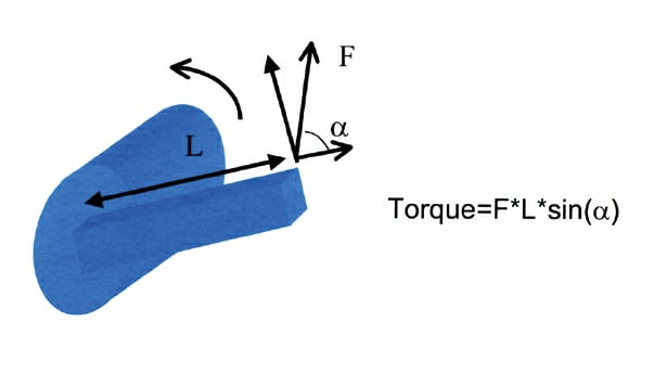
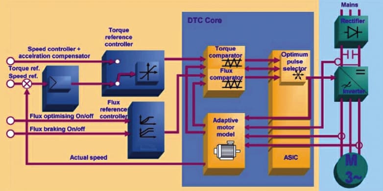
Direct Torque Control (DTC) is widely used as a method for controlling AC motors in many demanding applications. It is a unique method for controlling AC motors. In pulse-width modulation (PWM) drives, the output frequency and voltage are the primary control reference signals for the power switches, rather than the desired torque in/of the motor shaft. For those who are not familiar with inverter technology, the DTC principle can be illustrated most accurately via this mechanical analogy: the continuous calculation of the best angle at which to rotate a shaft, with a given arm length and the forces available. These electrical “force vectors” are generated with the help of semiconductor switches called Integrated Gate Bipolar Transistors (IGBT).

Testing Processes

Dynamometers should simulate the real highway precisely. This requires that, during acceleration and deceleration, the roll inertia be compensated dynamically to match the mass of the tested vehicle and the real road. To be able to realize such high-dynamic online compensation (real-world, real use), the load torque of the roll motor must be controlled accurately and with extreme precision at every speed point.
Testing gear-shifting-and-synchronization, calibration of automatic transmissions, clutching, and durability — these are typical testing needs. Inherently, these cases require a capability to change load torque very quickly. And, transmission test-stand configuration can include several motors — one simulating the engine, and two or even more for the simulation of the load. This requires mutual coordination of drives operation; the faster and more accurate it is, the better it simulates real-world conditions like differential-gear operation.
Drives with DTC technology can transfer speed/ torque information via ultra-fast optical links to each other. The speed torque signals can be used as reference to follower drives, to assess/react to desired load share (or as additional inputs to the main drive speed/torque reference). Additional complex functions to calculate speed/torque references to individual drives can be achieved within the DTC drive. This is useful in setting up and delivering testing in time-critical operations. The torque is calculated as a cross product between the stator flux and the stator current: T = Ψs × is . The stator flux is estimated from the stator voltage vector and the stator current: (2) Ψs = ∫(Us – Rs is ) dt . Six voltage vectors and two zero-vectors control the stator flux and the torque. The stator-flux amplitude is controlled to be constant.
For engine dynamometers, the dynamic performance is the key issue to ensure that you can simulate real systems dynamically and accurately. DTC drive technology answers this challenge directly. The test system’s overall dynamic performance can be quantified by looking at the delay from reference change to change in AC motor torque.

Once the torque reference is changed, DTC automatically selects the best voltage vector to achieve the desired torque, and checks every 25 μs if this vector is still the best one to maximize torque rise, or whether another vector should be used. The actual rise then is solely dependent on motor characteristics, such as leakage inductance. The torque rise time with a standard motor is between 1-2 milliseconds (ms), measured from current rise. For high-speed dynos, the leakage inductances are typically smaller, thus requiring shorter current- and torque-rise times.
The repeatability of testing is always important, but it is of particular importance when testing engines and complete cars for emissions. DTC has torque repeatability of less than ±0.5% of nominal torque. This means that the load applied will be the same time after time, and the measurement results from a test cell are comparable with each other. The benefits are reduced testing requirements, improved test data quality, i.e., reduced overall testing time.
Load Torque Accuracy and Linearity
In the DTC method, the status of the motor is evaluated every 25 μs by using measured signals and an advanced motor model. The AC current fed to the motor is measured every 5 μs, which means the torque calculated by formula is exact and up to date. DTC incorporates methods to identify motor design characteristics for each specific motor. These characteristics are the values for leakage and magnetizing inductances, stator resistances, and their saturation behavior. Thus, the motor model guarantees that the dynamics, accuracy, and repeatability are optimized, although the operational point might vary significantly (according to testing needs).
DTC has a torque accuracy of ±1.5% of nominal torque or better when encoder feedback is used, which is typical in these applications. Operating at low speed and torque, DTC allows the flux to be reduced, thus giving higher resolution at fractional torque levels. The speed accuracy is 0.01%. In DTC, all IGBT switch changes are based directly to the electromagnetic state of the motor. Optimal switching is determined for every control cycle at 25 μs intervals. That is also the main difference between Direct Torque Control and the traditional AC drive control methods. In DTC, there is no separate voltage and frequency controlled PWM modulator.
Via DTC technology, the torque and flux references are compared to actual values in hysteresis (digital switching between a defined range) controllers every 25 μs. The width of the hysteresis is very small and is controlled by the desired average switching frequency. This method generates no specific harmonic spectrum content with high amplitudes at a certain frequency but, rather, provides an evenly distributed power spectrum.
Linearity of torque means that, with a certain torque reference, the actual shaft torque must remain the same, regardless of the drive speed and torque (motoring or generating torque). For DTC, the non-linearity is ±1% of motor nominal torque, when encoder feedback is used.
Energy Savings and Safety
Regeneration also is an inherent part of test stands (energy generated from the motor, when the momentum of a load continues to turn the motor shaft). A common DC bus construction/ installation facilitates connection of several inverters to the same DC bus — so that another inverter also running the equipment under the test can directly use the power regenerated by the regenerating inverter. Fully regenerative inverters also can feed the energy back to the supplying AC network (grid or self-standing generating equipment). This means significant savings in energy cost.
When high speeds and high masses are involved, the safety of a complete test cell is an essential design aspect. A drive equipped with DTC ensures access to and operation of several built-in safety functions: over speed limits in torque control mode; limitation of torque; prevention of unexpected start; emergency stop; et al. For example, if the speed feedback signal from the encoder is lost, the DTC drive is able to recognize this within a few ms and automatically switches over to motor-model estimated speed — and gives either an alarm or fault signal to the operator. Most importantly, when this happens, motor acceleration to over-speed is prevented.
For more information, contact Ken Graber, marketing communications manager, ABB Inc., Low Voltage Drives, at ken.j.graber@ us.abb.com.

