
Mechanical CAD (computer-aided design) programs have become very sophisticated during the past few years. Unfortunately, there is still a portion of the engineering spectrum that cannot be handled well in a traditional CAD program: optical modeling. If you are creating a complicated optical system (think of a camera zoom lens), then it is best to perform almost all of the design in a specialized optical design software program and then transfer the optical design to a CAD program for the later stages of the design process where items like housings, threads, cams, and motors are designed and integrated into the model.
Interoperability and Data Integrity
Depending on the capabilities of the CAD and optical software, the design of a ring light model could follow four different workflows.
First, the model could be exchanged back and forth between the optical and CAD software using external data files or translators. Passing the model directly between programs would require either a common data file format or import/ export translators to translate from one file format to another. Using a common data file format would be ideal as long as the optical software program respected the integrity of the CAD data in the file, and vice-versa. Unfortunately, most software programs use proprietary formats. On the other hand, using translators to import/export solid models has a large drawback in an iterative workflow environment. Optical properties (i.e. reflective coatings) would need to be re-applied every time the model is imported back into the optical software, and mechanical design properties (i.e. tolerances and parameter dependencies) would need to be re-applied every time the model is imported back into the CAD software.
Second, the CAD and optical software could transfer model changes directly using data exchange protocols. DDE or COM protocols often are used to exchange data among Windows programs. This approach typically requires specialized macro programming to make sure that the desired data is transferred and applied on the receiving end.
Third, the optical software could work as a sub-program entirely within the CAD software (or vice versa). This approach typically limits the capabilities of the subprogram due to user interface, data manipulation, and memory management limitations of the “parent” program.
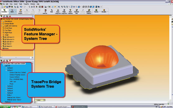
The final option is to have an approach where you primarily perform design work in program “A” and utilize a sub-program, or bridge program, to apply specialized properties for program “B”. Model transfer only goes one way (from “A” to “B”), but program “A” (in combination with its bridge or sub-program) maintains all properties for both programs “A” and “B”. Lambda Research has adopted this final approach through the development of TracePro Bridge for SolidWorks.
Practical Design of an LED Ring Light
While building the LED module model, it’s important that the optical design keeps track of every feature (e.g. thickness, radius, fillet, etc.). This allows the designer to change any individual feature at a later time, but requires the designer to treat each individual LED module as an assembly of components, with each component having separate properties.
Once the LED module design is complete, the designer can access the add-in bridge software to apply optical properties such as source definitions, glass or plastic materials, paints, surface roughness, and reflective coatings to each component. A property database shared by the optical design and bridge programs ensures instantaneous update and consistency among property definitions. Once the properties are applied to the LED modules (including the number and distribution of rays that they emit), the model is saved as a TracePro file within SolidWorks. The same file is opened in optical design software for comparison against module specifications through ray tracing and optical analysis.
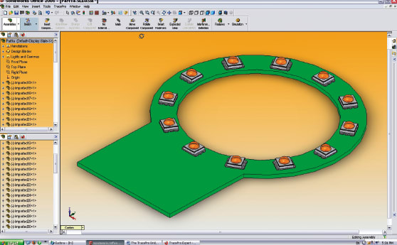
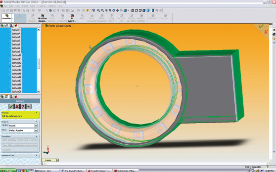
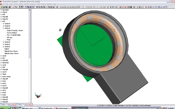
After the modeling is complete in the optical design software, the designer can integrate the LED models onto a PC board design (see Fig. 2), and continue designing the plastic housing in the CAD program, which will accommodate the requisite electronic components, including a power source (see Fig. 3). To complete the assembly, a ring of acrylic is provided as a protective cover for the LED modules. Since this cover can be formed into any number of shapes, it is common to use this cover to re-direct the light from the LEDs and is therefore called a “lens” (even though it might not look like your classic concept of a lens). The design of the electronics will not be considered here, but the outside of the housing and the acrylic cover lens can have properties applied to them through the bridge software.
Optical Analysis

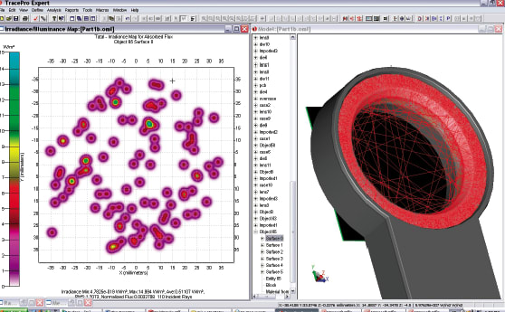
At this point, the design can be adjusted in the main optical design software package, including the number or type of LED modules, the height of the ring assembly, the cover lens shape (diffusing elements can be added), and the overall housing design. These changes can be driven by either optical or mechanical requirements such as beam pattern or ruggedness of the application. The simulation can then be redone and new results generated on the path to improving the camera’s ring-light design.
As this example shows, using an efficient optical design software that integrates with SolidWorks via add-in bridge software greatly reduces the amount of time designers spend moving back and forth between mechanical and optical design environments in an iterative design process, with the final result of shortening product design schedules and quickening time to market.
This article was written by Dr. Leo R. Gardner, Director of Marketing, and Patrick Le Houillier, Applications Engineer, at Lambda Research Corporation. For more information, contact Mr. Le Houillier at 978-486-0766.