Indium gallium arsenide, or InGaAs, is an alloy of gallium arsenide and indium arsenide. In a more general sense, it belongs to the InGaAsP quaternary system that consists of alloys of indium arsenide (InAs), gallium arsenide (GaAs), indium phosphide (InP), and gallium phosphide (GaP). As gallium and indium belong to Group III of the Periodic Table, and arsenic and phosphorus belong to Group V, these binary materials and their alloys are all III-V compound semiconductors.

Largely, the electrical and optical properties of a semiconductor depend on its energy bandgap and whether the bandgap is “direct” or “indirect.” The energy bandgaps of the 4 binary members of the InGaAsP quaternary system range from 0.33 eV (InAs) to 2.25 eV (GaP), with InP (1.29 eV) and GaAs (1.43 eV) falling in between. A semiconductor will only detect light with photon energy larger than the bandgap, or, to put it another way, with a wavelength shorter than the cutoff wavelength associated with the bandgap. This “long wavelength cutoff” works out to 3.75 μm for InAs and 0.55 μm for GaP, with InP at 0.96 μm and GaAs at 0.87 μm.

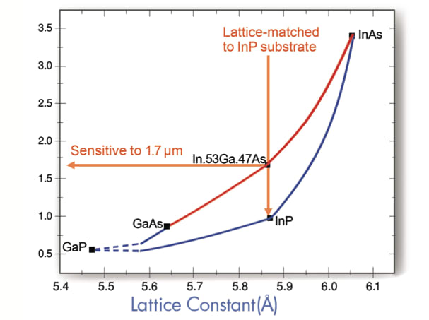
By mixing two or more of the binary compounds, the properties of the resulting ternary and quaternary semi-conductors can be tuned to intermediate values. The challenge is that not only does the energy bandgap depend on the alloy composition, so also does the resulting lattice constant. The lattice constants range from 5.4505 Å (GaP) to 6.0585 Å (InAs), with GaAs at 5.6534 Å and InP at 5.8688 Å. The relationship between the lattice constant and the long wavelength cutoff of the four ternary alloys in the InGaAsP family are shown in Figure 1.
The InAs/GaAs alloy is referred to as InxGa1-xAs, where x is the proportion of InAs and 1-x is the proportion of GaAs. The lattice constants and long wavelength cutoffs of these alloys are depicted as red lines in Figure 1. The challenge is that while it’s possible to make thin films of InxGa1-xAs by a number of techniques, a substrate is required to hold up the thin film. If the thin film and the substrate do not have the same lattice constant, then the properties of the thin film will be severely degraded.
For a variety of reasons, the most convenient substrate for InxGa1-xAs is indium phosphide. High-quality InP substrates are available with diameters as large as 100 mm. InxGa1-xAs with 53 percent InAs is often called “standard InGaAs” without noting the values of “x” or “1-x” because it has the same lattice constant as InP and, therefore, the combination leads to very high-quality thin films.
Standard InGaAs has a long wavelength cutoff of 1.68 μm. The material is sensitive to the wavelengths of light that suffer the least signal dispersion and degredation in glass fiber (1.3 μm and 1.55 μm), it detects “eye-safe” lasers (wavelengths longer than 1.4 μm), and it is the optimum wavelength for detecting the natural glow of the night sky.
Extended Wavelength InGaAs

Standard InGaAs has a long wavelength cutoff of 1.68 μm. Many applications require the detection of light with longer wavelengths. An important example is the ability to measure moisture content in agricultural products by measuring water absorption at 1.9 μm. Another example is LIDAR (light detection and ranging) used in airplanes to detect clear air turbulence. LIDAR systems often use lasers that emit light with a wavelength of 2.05 μm. InxGa1-xAs, with a longer cutoff, is called “extended wavelength InGaAs.”

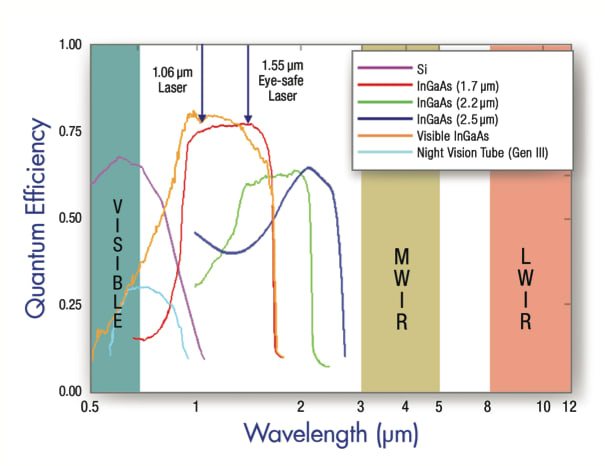
How is this created? Simply adding a little more InAs to the mix increases the lattice constant of the thin film, which causes a mismatch with the substrate, reducing the quality of the thin film. Figure 2 shows the quantum efficiency of standard InGaAs in blue, together with the quantum efficiencies of two extended wavelength alloys X=0.74 (green) and X=0.82 (red). The spectral response of silicon also is shown.
InGaAs in IR Imaging
InGaAs allows imaging in the SWIR, without requiring a cooling system to improve the signal-to-noise ratio. This allows for smaller, less expensive cameras that operate at lower power than most other IR imagers. Because the InGaAs cameras have non-uniformity corrections (NUCs) that last for the lifetime of the cameras, they are simple to operate and do not need new NUCs in the field.
The cameras and imagers are radiometric, so laser beam profiling and other quantitative measurements can be readily conducted with this imaging technology. InGaAs is a highly manufacturable material that allows high-volume production and low-cost cameras.
When imaging objects above 120 °C, the solid-state InGaAs shortwave infrared imaging cameras offer a distinct advantage over other IR detectors containing mid- and long-wavelength materials such as mercury cadmium telluride (HgCdTe) and indium antimonide (InSb). This thermal imaging benefit is put to use in hot processes like glassmaking and molten metal production. The InGaAs cameras can be used to image through plain glass windows in a variety of manufacturing industries. The imagers use standard glass optics or lenses, avoiding the challenge of other infrared cameras that require special optics or optical assemblies made of expensive materials such as germanium, sapphire, or silicon. InGaAs imagers do not require cooling, making them less expensive to run than thermal imagers (InSb, HgCdTe, or QWIPs) that require either liquid nitrogen or multi-stage thermoelectric coolers. InGaAs imagers also can image at high frame rates, which is a remarkable advantage over the uncooled bolometer technology.
Applications for InGaAs Imagers
There are many applications for InGaAs imagers, from military to commercial. In the military, the imagers are being used for imaging at night. They are capable of imaging light that is seen by current night vision technology, as well as light that cannot be detected by the current tube technology (see Figure 3). This permits the imagers to see “invisible” lasers that are currently being used on the battlefield. This digital imaging technology allows users to fuse multiple wavelength bands of information to help in the detection and identification of objects in the field.
In the commercial sector, InGaAs detector arrays are used in diverse applications, from imaging hot processes such as glassmaking, to monitoring the light on fiber-optic cable for telecommunication applications, to monitoring the quality of metals during molten metal processing. In industrial processes that use machine vision, InGaAs imagers provide the ability to image phenomenology that cannot be detected easily or at all in the visible wavelength bands.
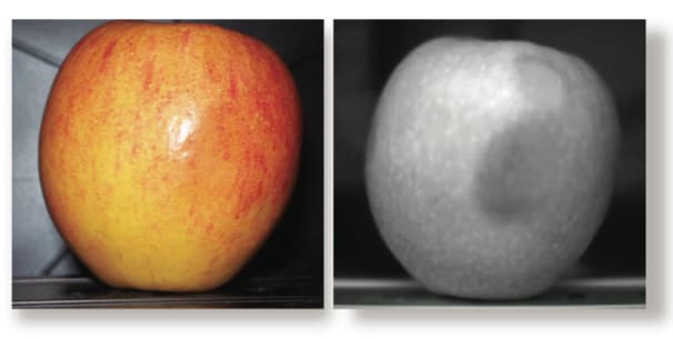
In the pharmaceutical industry, InGaAs imagers are now being used to detect liquid fill-levels in opaque bottles, instead of using traditional weighing methods. The food industry is using InGaAs imagers as an affordable alternative to silicon-based detectors to reveal the level of bruising in fruits and vegetables, as shown in Figure 4.
SWIR imaging provides a unique solution for non-destructive identification of materials, their composition, coatings, and other characteristics without the need for expensive and exotic optical materials.
This article was written by Dr. Marshall J. Cohen, President and CEO of Sensors Unlimited, Inc., Princeton, NJ.

