
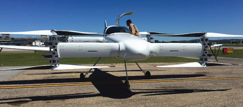
Beta Technologies (South Burlington, VT) has built a prototype Electrical Vertical Takeoff and Landing aircraft (eVTOL) and is putting it through the wringer. They are using wireless sensor systems from Parker LORD, MicroStrain® Sensing Systems (Williston, VT) to monitor the structures and functions of the prototype, both on a test stand and in flight.
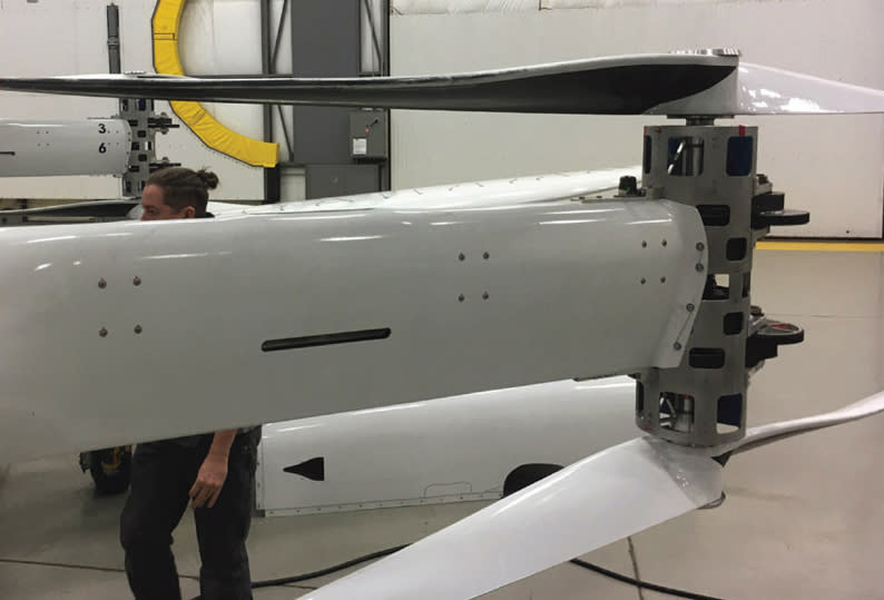
Although much of eVTOL development is directed to autonomous operation for applications such as air taxis, Beta’s niche application is with their seed customer — delivering human organs for critical transplant operations. Their proof-of-concept eVTOL is a piloted aircraft built on a standard aircraft frame. Weighing about 4000 pounds, with a 35-foot wingspan, it has eight 75kW motors for take-off and landing. The motors are paired to spin eight counter-rotating propellers that are used for lift in vertical takeoff. Once at elevation, the propellers tilt and the aircraft transitions into traditional flying mode. It is powered entirely by two 62 kWh lithium-ion battery packs (weighing around 1500 pounds) and designed for flight efficiency with a target maximum speed of 154 knots (177 mph) and a range of 150 miles. The test aircraft has so far achieved 72 knots, 100 ft elevation, and over 180 test flights approved by the Federal Aviation Administration (FAA). The aircraft design is currently piloted. A production aircraft will hold 3 – 4 people along with the organ transplant pod. Although the technology development is going well, there are still many regulatory hurdles with the FAA and others. Full commercialization is 3 – 5 years out.
The assignment for the MicroStrain team was to come up with sensor systems to monitor temperature, vibration, and strain on component bench tests and in flight. The wireless connection environment in this application is challenging. There are not only other high-power RF devices in proximity but for in-flight tests, the base station is located in a chase vehicle behind the aircraft as it takes off, hovers, and flies around the test area.
Test Stand Monitoring
Propeller thrust, vibration, strain, and load:
One load cell was attached to the propeller stand base to measure upward lift load over the range of propeller speeds.
Two accelerometers were attached to the propeller stand to measure vibration as a way to understand propeller balance characteristics at various speeds and with different propeller designs.
One tachometer measured RPM in order to produce synchronous Fast Fourier Transform (FFT) plots with the vibration sensors (to correlate accelerometer signals with the phase of the propeller blade).
Ten or more strain gauges mounted on the top and bottom surfaces of the propeller blades were used to measure strain from centrifugal load (stretch) and bending, at speeds of up to 1200 RPM and load in the range of 10klbs – 20klbs.

The data from these sensors were gathered via MicroStrain V-Link®-200 Wireless Sensor Nodes, each of which include eight analog input channels with onboard Programmable Gain Amplifier (PGA), filtering, and high-resolution analog to digital converter. The nodes, which can sample at rates of up to 4kHz, were used to monitor the propeller operating conditions with synchronized sampling.
Static load testing of airframe structures:
Strain gauges were mounted on the air-frame structures.
Hydraulic pumps with reference inline load cells were used to load critical points and areas of the structure
Gauges and load cells were also measured with V-Link-200 — this time at low sample rates.
Test Stand Plus In-Flight Monitoring
Vibration of hover motors:
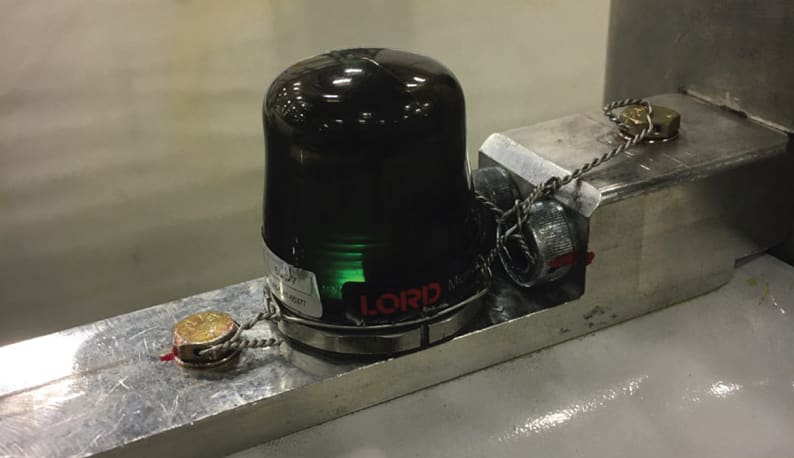
G-Link-200 battery-powered wireless 3-axis accelerometers were used for measurement of aerodynamically induced vibration, and detection of resonant frequencies.
The G-Link-200 was used to measure oscillation in the tail for conditions that could lead to aerodynamic flutter.
With a rugged, weatherproof, IP67 rated enclosure, the G-Link-200 provides extremely low noise, high fidelity waveform data at high sample rates. Its optional magnetic base allows it to be moved around in order to access detailed vibration data at different points.
In-Flight Monitoring
Flight control feedback and flight characteristics:
3DM-GX5-25 inertial sensors were used for triple redundancy in the flight control loop to provide pitch, roll, and angular rate values to the flight computer. The output of the flight computer controls the eight propeller motors, which were used in hover-mode.
These and other outputs of the inertial sensor, such as position and velocity were recorded on an SD card in an on-board computer to log “black box” metrics of the aircraft in flight.
The 3DM-GX5-25 is a small and lightweight, precision industrial Altitude and Heading Reference System (AHRS). It features a fully calibrated and temperature compensated triaxial accelerometer, gyroscope, and magnetometer. Dual on-board processors run an Auto-Adaptive Extended Kalman Filter (EKF) for dynamic attitude estimates.
In-flight temperature of primary battery cells:
Cylindrical lithium-ion battery cells, weighing a total of 1500 pounds, are arranged in six different packs distributed around the aircraft. This is a critical safety concern — lithium-ion batteries can be induced into thermal runaway and catch fire at about 70°C. Temperature probes were inserted into various locations in the pack assemblies to monitor battery temperature up to and during the eight-minute sustained hover power of about 500 kW.
Two TC-Link-200 nodes were used to monitor and transmit sensor data in real time.
The TC-Link-200 is a 12-channel wireless sensor used for precise measurement of thermocouples and differential output sensors. There is no calibration required. By selecting the desired thermocouple type, the node will output accurate, low noise temperature or mV data.
The Take-Away
It takes a heap of measuring to not only qualify a new aircraft, but to gather data to help improve the design based on real-world measurements. The task requires a suite of sensors that can not only make sensitive and accurate measurements of a wide range of critical data but should be able to transmit it wirelessly. Wireless sensors are especially well-suited to this task because they can be moved around to troubleshoot the design without having to worry about wiring. And, they can be installed on moving objects such as rotating parts and articulating joints in situations when live data is needed.
This article was written by Ed Brown, Editor of Sensor Technology. For more information, visit here .