
The software of a commercially available digital radio receiver has been modified to make the receiver function as a two-channel low-noise phase meter. This phase meter is a prototype in the continuing development of a phase meter for a system in which radio-frequency (RF) signals in the two channels would be outputs of a spaceborne heterodyne laser interferometer for detecting gravitational waves. The frequencies of the signals could include a common Doppler-shift component of as much as 15 MHz. The phase meter is required to measure the relative phases of the signals in the two channels at a sampling rate of 10 Hz at a root power spectral density <5 microcycle/(Hz)1/2 and to be capable of determining the power spectral density of the phase difference over the frequency range from 1 mHz to 1 Hz. Such a phase meter could also be used on Earth to perform similar measurements in laser metrology of moving bodies.
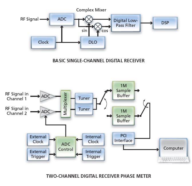
The specific commercially available two-channel digital receiver includes a dual-channel, 65-MHz, 14-bit peripheral component interface (PCI) bus dataacquisition card with a daughter board that contains a pair of narrow-band tuner integrated-circuit chips. The input stage of the card consists of two ADCs. In the tuner chips, input signals having frequencies up to 35 MHz can be translated to zero frequency, then digitally low-pass filtered to a bandwidth between 1 kHz and 1 MHz. The output samples of the tuner chips are fed to a two-part swap buffer. When each half of the swap buffer becomes filled up to a limit (e.g., 1M sample) specified by the user, the contents of the buffer are transferred, via PCI interface, to an external computer for further analysis.
The factory-supplied receiver software includes basic driver components and provides many options to control tuning frequencies, sampling rates, and other operational parameters. The phase-meter version of the software incorporates many of the basic driver components, but a significant effort was made in modifying other parts of the software to make the receiver function as a dedicated two-channel phase meter. In essence, the net effect of the modification is to cause the external computer to calculate differences between the phases in each successive pair of buffered samples from tuner chips and calculate the average phase difference over the time interval represented by the buffer contents.
This work was done by Martin Marcin and Alexander Abramovici of Caltech for NASA's Jet Propulsion Laboratory. For more information, contact