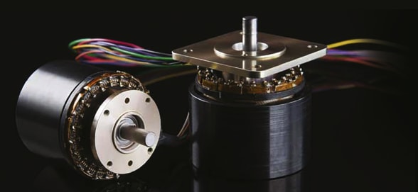
Permanent magnet brushless motors of various design architectures and power levels have been used since the late 1980s in industrial and commercial applications. Over the course of the past decade, motor manufacturers have developed and commercialized permanent magnet ring motors. The ring motor’s distinguishing features relative to the conventional permanent magnet brushless direct current (BLDC) motor is the motor’s tubular form factor, radial flux rotor design, and through hole.

Ring motor stators are offered both as iron core and ironless design architectures. The iron core ring motor stator shares more common features with the conventional BLDC; typically they consist of a slotted laminated stator back iron configured as a ring and wound with magnet wire. Ironless ring motor stators consist of electromagnetic stator conductors embedded in a cylindrical composite structure; this design results in a coreless cylindrical stator that can be coupled with a dual-rotor. These ring motor design options translate to different features relevant both to motor performance and system design.
Ring motors are available as frameless rotor and stator part sets in which the customer takes responsibility for design of the bearing and mount system, configured with an off-the-shelf mount and bearing system, or as a complete motion control solution in which the motor supplier and customer collaborate to integrate the frameless ring motor into the customer’s mechanism. The ring motor is an enabling technology for a wide variety of applications and markets due to its unique form factor and motor performance advantages relative to conventional BLDC motors.
Mechanical Design Flexibility

Ring motor manufacturers often facilitate development of custom motor hubs, shafts, and mounts that results in a level of motor-product integration unachievable with conventional BLDC motors. The center of a ring motor is hollow and this allows mechanism components to be located inside the motor. Rotors can be modified prior to final assembly to include a wide variety of accessories such as gears, bearing stops, screw-fastened attachments, welded-on attachments, locating pin holes, cooling features, and application-specific components.
Ring Motor Control
Control of ring motors is similar to conventional BLDC motors and falls into three categories of motor commutation: trapezoidal, sinusoidal, and vector. Choice of an appropriate commutation method is a complex issue dependent on the motor back EMF shape, pole count, and cost requirements. In general, motors with a sinusoidal back EMF benefit from the use of sinusoidal or vector control. For motors with a trapezoidal back EMF, trapezoidal control results in the highest system efficiency. Furthermore, trapezoidal control is the most cost-effective solution with only slight performance degradation relative to sinusoidal and vector motor controllers when driving motors with sinusoidal back EMF.
There are some special considerations for the control of ring motors. The high magnetic pole count associated with ring motors typically translates to a weight savings relative to conventional BLDC motors of similar power level because the rotor backing iron carries less magnetic flux and can be reduced in thickness. From a motor control perspective, high pole count translates to high motor controller commutation frequency. Motor controllers, especially sinusoidal and vector drives, have limited commutation frequency dependent on their processing power; controller commutation frequency is a consideration for engineers using ring motors with high pole counts.

Higher-inductance stators are typically associated with iron core ring motors and have a lower bandwidth of current control. However, the higher stator inductance reduces the transient current ripple of the controller, allowing for use of low-frequency pulse width modulation (PWM) control. The future of motor control is trending towards full compatibility with low-inductance motors as high-frequency PWM drivers become more prevalent. Higher-frequency PWM requires less inductance to maintain stable current control during high-frequency commutation, enabling lightweight, high-bandwidth ring motor systems.
High Power and Torque to Weight
Ring motors typically have high rotor pole counts, larger diameters, and superior cooling relative to their conventional BLDC counterparts. These features result in a variety of BLDC ring motor options with power-to-weight and torque-to-weight ratios exceeding those of a comparably powered conventional BLDC motor. This increased power-to-weight ratio coupled with the opportunity to save space, reduce components, and directly integrate a ring motor into an electomechanical product, makes ring motors an excellent choice for design engineers.
Ring Motor Applications
Electomechanical product design utilizing ring motors benefits from a variety of opportunities to directly incorporate the product’s rotating mechanisms with the motor rotor. Ring motor customers include optical scanning system manufacturers that directly integrate optics with the motor rotor, pump manufacturers that are able to eliminate redundant bearing sets while directly driving the pump, and unmanned aerial vehicle (UAV) manufacturers that integrate the motor rotor with the vehicle propulsor. The ring motor is an enabling technology for innovative mechanical configurations and system designs with a multitude of markets and applications that can benefit from use of the technology.
This article was written by Evan Frank, Chief Technical Officer, and Joseph Kay, Electromechanical Engineer, at ThinGap (Ventura, CA). For more information, Click Here .

