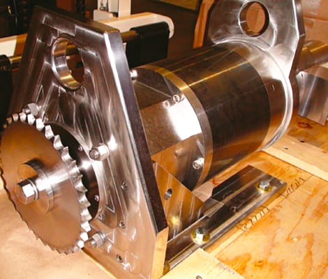
Deep-sea remotely operated vehicles (ROVs) present motion control design engineers with some difficult challenges. Applications may include ROV propulsion, position thrusters, dive vanes, rudders, or robotic arms. Some problems are common to all of them.

It is not possible to make the entire assembly of this material since metal fittings and hardware have to be carefully selected and protected to avoid galvanic corrosion that occurs when dissimilar metals are in contact with each other when wetted with seawater. At the same time, connectors, cables, gaskets, and seals need to be of suitable materials, and they must be properly installed to avoid leaks. Standard machine operations that result in spiral metal finishes can result in seal seepage despite meeting RMS requirements for metal finish. Corrosion, sand, mineral deposits, and marine life can cause additional problems if they are not considered in the product design.
Pressure. Depending on the intended depth of operation, pressure can be substantial. For the US Navy, 5000 PSI is a common specification. At such pressure, standard sealing techniques fail. By providing oil-filled, pressure-compensated units, equalizing internal and external pressure allows a smaller unit to be deployed, as the vessel walls need not support large differential pressures. But there is more to this than simply filling a unit with oil. A common sealing technique is a double seal or a double-lipped seal. The assumption behind this is that if one seal fails, the second is there to prevent failure. However, in a high-pressure situation, the space between the two seals becomes a failure point. Internal to the motor assembly, any void such as an air bubble in the varnish of the motor winding is a potential failure point. Under pressure, the bubble collapses, and hardened varnish cuts the wire. Other components such as Hall Effect switches must be built to withstand the pressure, or they will fail.
Fluid expansion. Once the unit is full of oil and is pressure-compensated, operating at depth is viable, but applications typically require that the units operate out of the water as well as being submerged. Operating in air, the motor heats up, the oil expands, and unless it is well designed, the internal pressure blows the seals out of the unit before it ever gets to the sea.
Low voltage. Nearly all of these ROVs are battery operated; since salt water is conductive, a commonly used voltage is 24 VDC, as this voltage does not represent a danger to the people working on the equipment. However, to get any substantial amount of power, the current has to be quite high, and copper losses increase as the square of the current. Further, the voltage generated by the spinning magnets in the motor (back electromotive force, or BEMF) puts a significant limit on the top speed of the motor.

Cable length. A typical starting point for a design concept is to have the electronics above the water, with an umbilical cable that goes to the ROV. But the practical issues involved with this become apparent when doing the math. If the motor is to provide five horsepower, or 3,730 Watts of power at the output shaft, at 24 volts this is 155.4 Amps if the motor is 100% efficient and there is no cable loss. A 2,500-foot-long cable has 5,000 feet of wire in the circuit. A conductor suitable for 155 Amps is an AWG 1 — this wire has a resistance of 0.1239 ohms per 1,000 feet, so this 5,000-foot conductor would have a resistance of .6195 ohms at 155 Amps, and the voltage loss in the cable would be 96 Volts. But if one had 24 Volts to start with, the system will not work. To overcome this problem, larger cables can be considered, but the weight of the cable becomes unmanageable. Alternatively, higher voltages can be used, but this creates battery issues.
A common solution is to place the motor drive electronics and power supply in proximity to the motor. This is accomplished by using a “dry tank” that is completely sealed and built to withstand the expected pressure. Electrical fittings rated to 20,000 PSI are available. Batteries need to be in separate compartments so the fumes do not attack the electronics.
Connectors. For a number of reasons, connectors are desired on the motor assemblies. There are dry mate and wet mate versions. The dry mate units are waterproof once they are assembled, while wet mate versions can be assembled wet and still be expected to function. A common issue is the size of the connectors, as they are quite large.
A fairly common error that is made is the result of assuming that the cable jacket is all that needs to be sealed. However, if the individual conductors and the spaces between the conductors are not blocked, oil from the motor under high pressure will flow into the cable, and the pressure compensation of the motor will be lost. If there are any pinholes in the cable jacket, seawater will fill the spaces and the salt water will short out the conductors. Proper cables and connectors for deep-sea applications are relatively expensive and are a common failure point.
Size and weight. Since most of the applications are for mobile devices, the size of the assembly and the overall weight are design issues. Frequently it is necessary to work around existing mechanisms requiring creative mechanical designs in addition to the challenges mentioned above.
After working on a number of deep-sea design projects, the common thread has been that initial estimates of speed and power are typically off by orders of magnitude. The size, weight, and cost of meeting the requirements become unacceptable, and eventually the speed requirements are reduced to the point where a solution becomes practical.
This article was written by Richard Halstead, President of Empire Magnetics, Rohnert Park, CA. For more information, Click Here .

