
A compact, high-dynamic-range, electronically tunable vector measurement system that operates in the frequency range from ≈560 to ≈635 GHz has been developed as a prototype of vector measurement systems that would be suitable for use in nearly-real- time active submillimeter-wave imaging. A judicious choice of intermediate frequencies makes it possible to utilize a significant amount of commercial off-the-shelf communication hardware in this system to keep its cost relatively low. The electronic tunability of this system has been proposed to be utilized in a yet-to-be-developed imaging system in which a frequency- dispersive lens would be used to steer transmitted and received beams in one dimension as a function of frequency. Then acquisition of a complete image could be effected by a combination of frequency sweeping for scanning in the aforesaid dimension and mechanical scanning in the perpendicular dimension.
As used here, “vector measurement system” signifies an instrumentation system that applies a radio-frequency (RF) excitation to an object of interest and measures the resulting amplitude and phase response, relative to either the applied excitatory signal or another reference signal related in a known way to applied excitatory signal. In the case of active submillimeter- wave imaging, the RF excitation would be a submillimeter-wavelength signal radiated from an antenna aimed at an object of interest, and the response signal would be a replica of the RF excitation as modified in amplitude and phase by reflection from or transmission through the object.
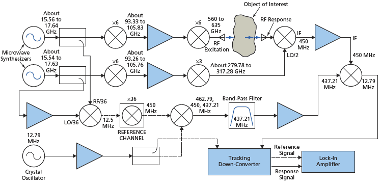
The system is depicted schematically in the figure. The ultimate sources of the RF excitation and reference signals and of local-oscillator (LO) signals for use in down-conversion of the response signal are two compact, inexpensive microwave synthesizers that are electronically tunable over the frequency range from 14 to 18 GHz in increments of 250 kHz. The outputs of both synthesizers are multiplied ×6 in frequency. The resulting signals, having frequencies in the neighborhood of 100 GHz, are amplified ≈20 dB by a pair of monolithic microwave integrated-circuit (MMIC) amplifiers. Then one of the amplified signals is further multiplied ×6 in frequency for use as the RF excitation signal, while the other is further multiplied ×3 in frequency for use as the LO signal in a sub-harmonically pumped mixer.
The RF excitation signal is radiated and made to pass through or reflect from an object of interest, and the response signal is mixed with the aforementioned subharmonic LO signal to generate a down-converted signal [denoted an intermediate frequency (IF) signal in the radio art]. The RF and LO synthesizers are controlled from a laptop computer, which adjusts their frequencies to keep the IF constant at 450 MHz. Thus, the RF- and LO-synthesizer outputs differ in frequency by 450/36 = 12.5 MHz.
The phase and amplitude measurements are performed indirectly, on signals derived from the IF signal, rather than directly on the RF response signal. For the purpose of generating a phase reference signal, portions of the outputs of the RF and LO synthesizers are mixed, yielding a 12.5-MHZ signal, which is then multiplied ×36 in frequency to obtain another 450- MHz signal. This 450-MHz signal cannot be used directly as the phase reference signal because the outputs of the inexpensive microwave synthesizers have such poor phase-noise characteristics that this signal and the 450-MHz IF signal are indistinguishable from the accompanying phase noise. Therefore, it is necessary to perform further processing as described next.
In particular, it is necessary to further reference both the 450-MHz IF and the 450-MHz reference signal to a stable source before detection. This involves down-converting the raw 450-MHz reference signal by 12.79 MHz by use of a 12.79- MHz fundamental crystal oscillator, a mixer, and a band-pass filter. The resultant 437.21-MHz signal is then mixed with the 450-MHz IF signal. Inasmuch as the phase noises of the 437.21-MHz signal and the 450-MHz IF signal are totally correlated, mixing these two signals cancels out that noise, leaving a 12.79-MHz signal that has the same amplitude and phase characteristics (minus the synthesizer noise) as does the 450-MHz IF signal.
It should be noted that any 450-MHz signal passing through the 437.21-MHz bandpass filter would be down-converted along with the 437.21-MHz signal, resulting in cross-talk and loss of dynamic range. It is therefore essential that the 437.21-MHz band-pass filter have extremely high rejection at 450 MHz.
The 12.79-MHz signals in the response and reference channels are converted to a frequency of ≈66 kHz in a tracking downconverter, then detected by a lock-in amplifier that functions as a variable-bandwidth magnitude and phase receiver. The bandwidth and gain are controlled by a laptop computer. The vector DC outputs of the lock-in amplifier are read by an analog data-acquisition card in the computer, wherein these readings are converted to polar format. At maximum detection bandwidth, real-time acquisition speeds of >3,000 points per second are possible.
This work was done by Robert Dengler, Frank Maiwald, and Peter Siegel of Caltech for NASA’s Jet Propulsion Laboratory. For more information, download the Technical Support Package (free white paper) at www.techbriefs.com/tsp under the Electronics/Computers category.
In accordance with Public Law 96-517, the contractor has elected to retain title to this invention. Inquiries concerning rights for its commercial use should be addressed to:
Innovative Technology Assets Management
JPL
Mail Stop 202-233
4800 Oak Grove Drive Pasadena, CA 91109-8099
(818) 354-2240
E-mail: This email address is being protected from spambots. You need JavaScript enabled to view it.
Refer to NPO-43394, volume and number of this NASA Tech Briefs issue, and the page number.
This Brief includes a Technical Support Package (TSP).
600-GHz Electronically Tunable Vector Measurement System
(reference NPO-43394) is currently available for download from the TSP library.
Don't have an account?
Overview
The document outlines NASA's development of a compact 600 GHz Electronically Tunable Vector Measurement System, which is designed for submillimeter wave imaging. This system represents a significant advancement in measurement technology, particularly in the field of aerospace and related applications.
The Technical Support Package is part of NASA's Commercial Technology Program, aimed at disseminating results from aerospace-related developments that have broader technological, scientific, or commercial implications. The document references a specific paper authored by R.J. Dengler, F. Maiwald, and P.H. Siegel, which was published in the Microwave Symposium Digest in June 2006. This paper provides detailed insights into the system's design and functionality, spanning pages 1923-1926 of the publication.
The 600 GHz measurement system is notable for its electronically tunable capabilities, allowing for precise measurements in the submillimeter wave range. This technology is crucial for various applications, including advanced imaging techniques that can be utilized in scientific research, telecommunications, and other fields requiring high-frequency measurements.
The document also includes contact information for further inquiries, specifically directing interested parties to the Innovative Technology Assets Management office at NASA's Jet Propulsion Laboratory (JPL) in Pasadena, California. This office can provide additional assistance and information regarding research and technology in this area.
It is important to note that the document contains proprietary information and is subject to U.S. export control regulations. As such, users are advised to comply with all applicable regulations when utilizing the information contained within.
In summary, the document serves as a technical overview of a cutting-edge measurement system developed by NASA, highlighting its potential applications and providing avenues for further exploration and inquiry into the technology. The 600 GHz Electronically Tunable Vector Measurement System stands as a testament to NASA's commitment to advancing aerospace technology and its applications in various scientific and commercial domains.