Direct drive servo motor and drive technology has many advantages. It reduces an axis’ parts count, mechanical losses, and often its objectionable noise. What’s more, it also increases the machine’s efficiency, lowering operation cost for the user due to its inertia ratio as compared to the more common mechanically advantaged multi-body axis designs. Reducing the mechanical transmission components (gearboxes, timing belts, pulleys, cams, lead screws, etc.) between the motor and its load is only part of the savings.

This article presents a determinate measure for managing energy utilization of a servo motor during a machine’s design. This determinate measure of inertia ratio, J_load/Jm, is presenting the energy saving potential for dynamic applications as a function of an axis’ inertia ratio, which is typically broadened in direct drive servo applications. However, with use of good mechatronic concepts during a machine’s design, mechanically advantaged servo axes can also provide significant energy cost savings.
Maximize Energy Savings with a Determinate Measure
The potential energy savings of any dynamic servo axis can be determined by a comparison of its inertia ratio, where all acceleration and deceleration energy is transmitted to the load (J_load/Jm=∞), against the maximum power transfer ratio (J_load/Jm=1), where only half the acceleration and deceleration energy is transmitted to the load. Maximum energy savings is best achieved with a minimal Jm (theoretically when J_load/Jm=∞, not a matched J_load to Jm).
The inertia ratio (also called moment of inertia ratio or inertia mismatch) for a rotary servo system can be divided into two main parts: (1) the total moment of inertia of the load (J_load) of all the axis’ components (reflected back through the mechanism when applicable) summed together at the motor’s shaft, and (2) the motor’s moment of inertia (Jm).
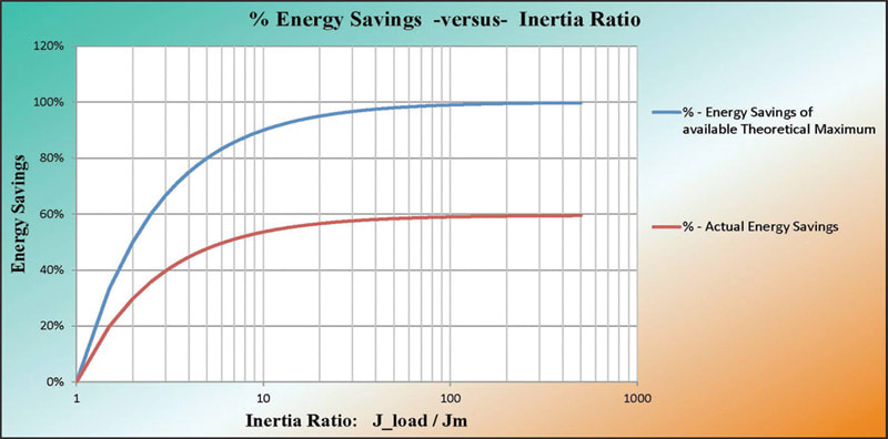
The ideal inertia ratio is presented in many technical manuals to be 1:1 (where J_load=Jm). This ratio is the ideal inertia ratio limit for maximum power transfer (evenly splitting the acceleration and deceleration energy with the motor) to minimize potential control loop issues. However, it undesirably maximizes energy utilization in dynamic applications. The other ratio, J_load/Jm=∞, presents maximum theoretical efficiency for any given axis under evaluation. Comparing this best possible theoretical inertia ratio against the maximum power transfer ratio provides a determinate measure for energy management (Figure 1).
An axis’ energy savings is maximized when as much electrical energy as possible is expended on the actual load. The lowest possible power requirements of an axis are achievable when the machine designer looks for the maximum acceleration/deceleration of the load inertia, while also considering the system’s limitations and capabilities for the axis stability, controllability, performance, accuracy, repeatability, and so on.
Even though most servo motion control axes that approach a 1:1 inertia ratio are less likely to have control-loop instabilities, an application’s ideal moment of inertia ratio is much more fluid than a fixed number or range. That is, each axis’ ideal inertia ratio depends on the actual process to be performed, its mechatronic solution, and application. Other factors include such components as the specific axis’ motion profile and dynamics, friction, stiction, external loading, backlash, compliance and stiffness, loads, mechanism inertia, feedback resolution, and number of moving mechanical bodies between the load and motor. Further considerations include natural frequencies of the design, the motor’s drive Pulse Width Modulation/Space Vector Modulation (PWM/SVM), and any applicable controller update rates. For closed-loop mechanisms, all these design factors come into play when considering operation and stability.
Optimal Inertia Ratios Allow for Increased Energy Savings


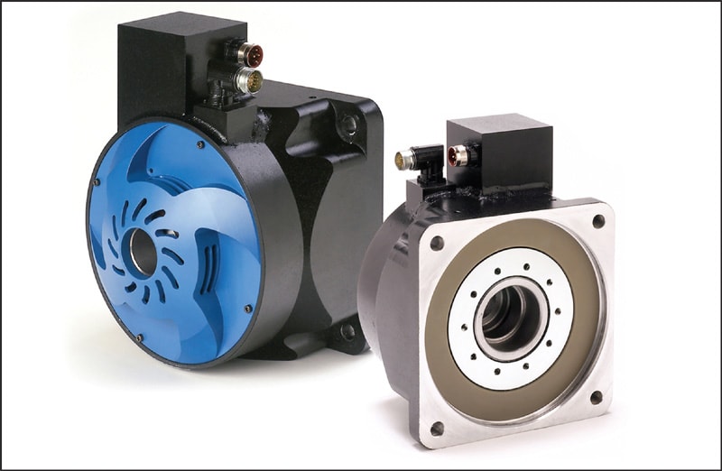
These dynamic applications, whether indexing and/or providing constant high-speed correction, can achieve substantial energy savings using today’s direct-drive servo technology’s advanced digital drive capabilities with faster processor speeds and update rates, flexible filtering, and high feedback resolution capability (from 221 bits [2,097,152 counts] up to more than 227 bits [134,217,728 counts] per motor revolution); together yielding high system bandwidth (BW) response times. These advanced drive capabilities, coupled with the best mechatronic designs, provide higher control capability for the utilization of direct drive servo technology. Today’s servo industry has enough control over a typical dynamic application to assume the effects of the figure of merit (J_load:Jm) to be of minimal consequence. Unlike a typical mechanically advantaged system, the inertia ratio of the direct drive servo is often limited to the compliance of the steel between the motor and load, the machine’s frame stiffness, feedback resolution, and available system BW (Figure 2).
Direct drive technologies have led to higher control-loop gains (which lead to higher BWs), greatly enhancing the servo system’s capability to catch and control possible axis instabilities before they become problematic (or cause other machine instabilities such as resonances). In good mechatronic axis designs, these relatively new digital drive capabilities are allowing direct-drive servo motors with high-resolution feedback capabilities to take advantage of the available energy savings.
Dynamic Applications Create an Energy Savings Opportunity
Whether a direct-drive servo axis or a mechanically advantaged servo axis, the actual process times are often fixed and cannot be decreased under the existing process technology. Therefore, the product or workpiece transfer times are the only times that can be decreased within the subject-matter production cycle. This is the base topology used for determining potential energy savings for dynamic servo applications as a function of an axis’ inertia ratio. Thus, the process time is assumed fixed and held constant, forcing a reduced transfer time to make a specific move. The faster rate results in an increase of the specific axis’ peak horsepower (HP) requirements during the acceleration and deceleration times, from its baseline production rate by the product of the increased ratio of both speed and torque.
This specific method allows for each calculated motion profile, as a function of a fixed peak torque (X•Trms), to have a constant traverse RPM velocity (N) and a constant RMS equivalent velocity (N_rms), regardless of the inertia ratio. The relative (J_load/Jm=∞ versus J_load/Jm=1) available percent (%) energy savings, regardless of the value of X chosen (within system limits), approaches a theoretical maximum of approximately 60%.
Consequently, the industry can pinpoint an inertia ratio range for an axis’ most efficient energy utilization for dynamic high-speed type applications (with stability concerns set aside), while maintaining good risk management. Any manufacturing process, run at a faster rate for improved throughput, requires a machine with the capability to move and/or act on the product faster, and to respond to all commands and disturbances within the limit of the product and/or the process itself to maintain quality.
Individual servo axis systems that can best achieve the available energy savings are those that are continuously on the move, whether their motion profile commands are constantly changing due to indexing requirements or constantly changing due to dynamic load disturbances.
Mechanically Advantaged Axes
For an exceptional machine design, the mechatronic engineer must contend with backlash and/or compliance within the driven components, which still limits the inertia ratio range as a function of stability (the typical inertia ratio, where axis stability may still be achieved). The inertia ratios (J_load:Jm) 8-20:1 yield ~87.5-95% of the available 60% energy savings as compared against the maximum power transfer ratio of 1:1. These energy savings ratios are achievable with high-resolution feedback and high BW drives when the mechanics of the system are designed with minimal compliance and backlash within the drive train and machine frame. Even ratios up to 30:1 are possible with some mechanically advantaged applications.
These higher inertia ratios of non-direct-drive systems require a good to top-notch mechatronic design to minimize compliance, depending on the process/work to be performed. It is this overall increased system stiffness that allows for the higher inertia ratios with the lower risk of instability, making the potential energy savings possible with high-resolution feedback and increased drive capability. Consequently, if an induction motor were replaced on an axis typically designed for an induction motor, the controlled axis cannot be expected to perform as if originally designed for servomotor utilization, whether there is a higher inertia mismatch or not.
Direct Drive Axes
In contrast, the compliance of a directly driven axis is essentially limited to the driven components and frame. For direct drive servo motor axes, the inertia ratio can easily exceed a 30:1 ratio yielding ~97% energy saving (of the theoretical maximum). Therefore, the typical direct drive axis with a 200:1 to 300:1 inertia ratio approaches 100% achievement of the theoretically available ~60% energy savings. Compliance still limits the inertia ratio range as a function of stability, but this compliance is now set by the driven material between the motor and load (typically steel) and the machine frame (steel, cast iron, etc.). Therefore, the axis’ lack of compliance (stiffness) allows for much higher direct drive inertia ratios with little risk of stability issues, with high-resolution feedback and high BW drive capability. The required stiffness often demands larger shafts and bearings, and even the compliance of the machine fixture/stand holding the motor comes into play. Indexer style applications with inertia ratios of 1600:1 have been successful with a feedback resolution of 224 (16,777,216) and greater.
In addition to achieving nearly 100% of the available energy savings, even further cost reductions are realized by the lack of mechanical transmission components, allowing for a cleaner mechanical assembly, lower parts count, and smoother and quieter operation. Additional benefits include improvements in precision, throughput, reliability, Mean Time Between Failures (MTBF), and lower system maintenance.
Are Energy Savings Worth the Cost of Changing?
Whether using a direct drive or mechanically advantaged axis with the identified higher inertia ratios for best possible energy savings, it is up to the OEM/end user to decide if there are enough energy savings to consider the options for change. For example, the replacing of a fractional hp (horsepower) servo motor will not have the energy savings impact of replacing a 30 hp servo. However, a quantity of 50 to 100 axes will likely make a significant difference in energy utilization, even if each motor is less than 1 hp (746 watts). So, the actual savings will be more noticeable for larger servo motors, especially when there are multiple axes and/or multiple machines.
Conclusion
Dynamic applications, whether indexing and/or providing constant highspeed correction, can achieve substantial energy savings with their lower power consumption in a wide variety of direct-drive machine applications and solutions. Proper motor-drive-feedback selection of a servo-controlled axis is possibly the single most significant savings element a machine designer can make for reducing the user’s operational cost.
This article was written by Hurley Gill, Senior Applications/Systems Engineer for Kollmorgen, Radford, VA. For more information, Click Here .

