
While growing up, many of us were fascinated by watching gears turning, whether in bicycles, clocks or — like me at six — garbage trucks packing trash on the old rear-load machines. Today, gearing systems play a crucial role in machinery, transmitting power efficiently and reliably across a wide range of applications.
Over decades of industrial evolution, numerous gearbox types have been engineered to meet specific performance requirements and remain indispensable in modern equipment. Among these, planetary gearing stands out with its unique design and capability set. This article explores the fundamentals of gearing types with a particular focus on the planetary servo design, highlighting key features and why they continue to be essential in automation and industrial operations.
Gear Engineering
Let’s start with a few core principles of gearing. To keep it simple, we won’t detail the housing design and shaft configurations here but will concentrate on the internal gear sets that deliver the torque. The output speed and torque requirements determine the ratio and the gear case size. It is important in the application process to design gearing capable of delivering the output speed and the desired torque. Many failures happen when the output torque is not reviewed closely.
A constant to remember when sizing speed reducers is that as speed decreases, torque increases. The housing and shaft configurations are vital, and with countless combinations available today, taking the time to make these considerations is crucial so the gearbox is capable of delivering the required speed and torque.
Common Gearing Types
Planetary gears
There are thousands of configurations from numerous manufacturers available in the marketplace, but planetary gearboxes are the most frequently recommended in most automation designs. Why?
Planetary gearboxes excel with their:
Compact design
High torque
Low backlash
Accurate, repeatable movement
High efficiency
Quiet operation compared to other gear types
Input speeds up to 4,000-6,000 rpm
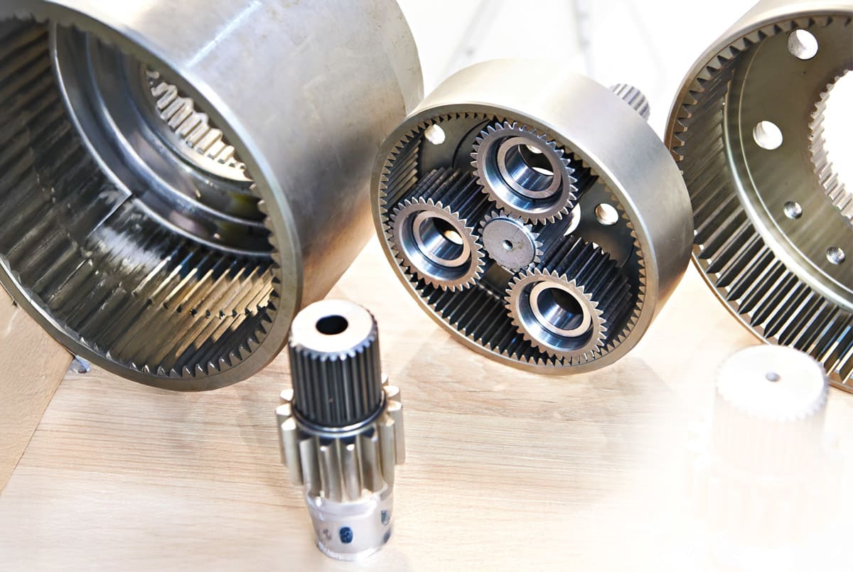
Before diving deeper, we should define “backlash,” which is the gap or clearance between the mating gears’ teeth. Low backlash, along with these other features, is critical for precision control in automation. Robotics, as well as applications including aerospace, automotive, and material handling equipment, commonly feature planetary gearboxes. Smaller-scale systems such as motorized blinds found in homes and offices benefit from the planetary gearbox’s compact size and quiet operation.
The planetary design distributes the load across multiple gears, reducing gear wear and enabling heavy loads, making it useful for applications such as conveyors. In addition, this design operates at up to 98 percent efficiency in some applications. The design consists of a center or sun gear, surrounded by multiple planet gears and an outer ring, with the helical tooth profile as the most popular.
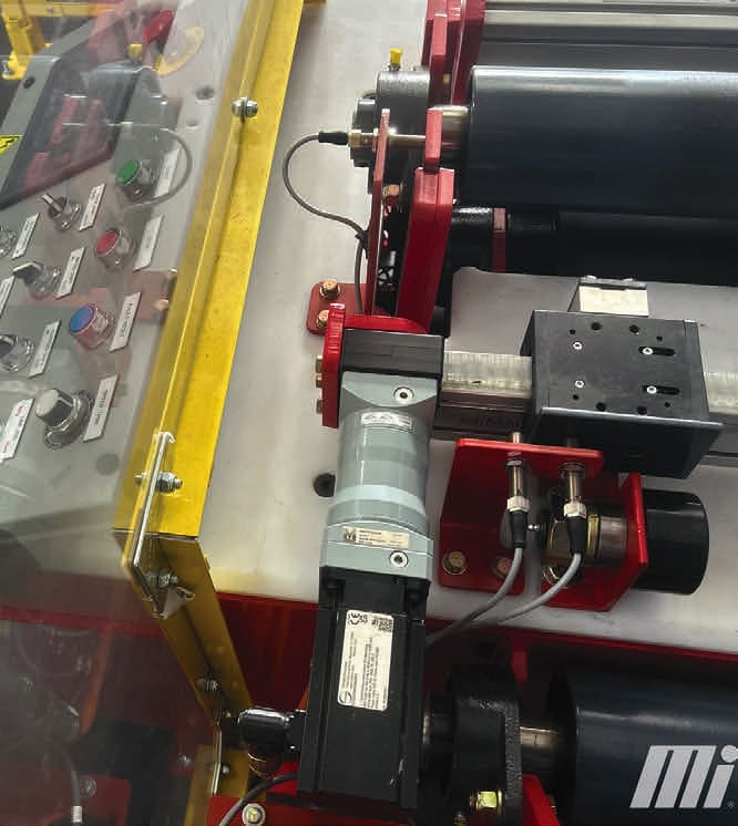
Multistage gear reducers are utilized to achieve higher reduction ratios. The motor of choice is the servo, which will easily couple to the gearbox for precise and controlled motion (Figure 1). The most common servo gear unit is the coaxial or inline. However, if a right-angle configuration is needed, the helical bevel gearing units are available.
Helical gears
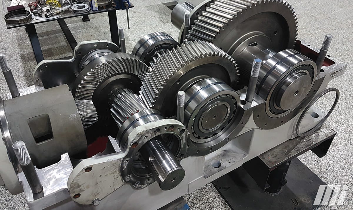
The helical gear design is the heart of the planetary servo gearbox. However, helical gear sets are also used in other gear reducer styles. Few application engineers or designers would dispute the benefits of this type of gearing. Helical gears (Figure 2) are very quiet, operate smoothly and have very low backlash. They provide efficiency and a high load capacity.

The angled teeth engage and disengage gradually rather than all at once, as with straight-cut gears. This gradual engagement reduces vibration and noise, while handling higher shock loads. In industrial applications, helical gears can transmit power between parallel shafts, non-parallel, coaxial or cross shafts. In addition, reliability engineers appreciate the longer lifespan common for helical gears. In automation, the servo gearbox we see most is the planetary helical gearbox in a coaxial or right-angle orientation.
Spur gears
The most common type of gearing across industry is the spur gear, which can be considered the backbone of mechanical transmission. The gears feature straight teeth and are suitable for low-to-medium speed applications where efficiency and noise are less critical. Spur gears are used for many applications, from home goods and office printers to automobiles and agriculture. Increasingly, the spur gear is also utilized in medical and robotics applications.
Miter gears
Miter gears are a common, basic type of gearing, always with a 1:1 ratio. Their main purpose is to change the orientation of shafts by 90 degrees. Despite their simplicity, they are very efficient, compact and precise with minimal backlash. It is another style found in automobiles, aerospace and manufacturing. The most common applications are in industrial machinery, and they are frequently found in valve actuators.
Worm gears
The worm gear consists of a threaded worm made of steel, which meshes with a bronze worm wheel. Many worm gears feature a 90-degree angle output shaft from the motor input. The simple design can also be manufactured in multiple reductions or stages to obtain lower output speeds. Used in many conveyor applications, worm gears have the advantage of high ratios in a compact size. The most notable disadvantage of this gear type is its inefficiency. It gets worse as the ratios get higher and with additional or multiple stages of reduction. They produce more heat because the worm slides across the worm wheel, making a lubrication plan essential to maintenance. In applications requiring more efficiency and smaller input horsepower, worm gears are being replaced by the helical bevel design, which provides a longer life than traditional worm gears.
Bevel gears
Bevel gears (Figure 3) are designed to transfer power between nonparallel shafts such as a right-angle gearbox. The most common applications are automotive (especially in rear differentials), aviation, hand tools and industrial. In the industrial applications, these are seen inside cooling towers, pumps, packaging machinery, and other equipment. This design can be engineered to handle high speeds with reduced vibration while accommodating high torque loads.
Rack and pinion gears
Another type of gearing for linear movement is the rack and pinion, which is widely used due to its simplicity, precision and efficient use of space. The gear rack converts rotation into linear motion. This style plays a critical role in CNC machines, automation applications and many industrial robots. If linear motion and accuracy are required, the rack and pinion can provide a solution. As with many styles of gearing already presented, the technology is not new but continues to have its place in industry.
There is a gearbox style commercially available for almost any application in industry today, with custom designs manufactured to order. Many gearboxes are supported by knowledgeable manufacturing and distributor representatives to ensure proper selection and system integration. As with all machinery and equipment, a robust lubrication and maintenance program is essential to long-term reliability. Facilities that leverage reliability-centered maintenance programs, along with proper selection and installation, can expect many years of dependable service from their gearing systems.
This article was written by Brandon Brownlee, a Food & Beverage Industry Specialist for Motion (Birmingham, AL). For more information, visit here .