

Wireless transmission of data from networks of sensors is vital to industrial automation and predictive maintenance systems — the more data, the more effective the systems. The problem is that it takes more power to transmit more data — so powering these sensors is a major challenge. Batteries can be effective, but eventually they have an end of life and must be replaced, so someone has to go around to every sensor and physically change its battery. And many of the sensors are in locations that are hard to access or are in hazardous environments. So, it would be better to power the sensors without using batteries. This can be done by harvesting energy from a sensor’s environment, often heat, vibration, or light. The amount of energy from these kinds of sources, however, is quite limited.
Now, MIT researchers have developed a method that anyone can use to design an energy management interface between the harvester and the sensor load to minimize the drain on the harvester and maximize the amount of data that can be transmitted by the sensor.

The following is excerpted from a discussion with Daniel Monagle and Steven B. Leeb who, along with Eric Ponce, are members of the MIT team that developed and demonstrated the methodology. The discussion covered the design parameters for developing an energy management circuit that could be used with any power harvester. It also covered the specific requirements for the clampable, split-core current transformer magnetic energy harvester they used for their demonstration project.
Tech Briefs: Can you give me an overview of your project.
Monagle: There are really two key contributions. The first is the broader framework of how to approach designing an energy management circuit. We propose the following design tenets:
You need circuits that can boot themselves up without a battery or some stable energy source.
You need storage on the circuit board to make sure the sensor can run without a battery even when no harvesting is present.
You need to avoid making these sources too large. To avoid making these things impractically large, you want to have some sort of microcontroller action or some algorithms that run in real time to enhance your power harvest.
Our second contribution is more specific to our prototype. We’re using a magnetic energy harvester that’s a split current transformer core. It harvests relatively large amounts of energy compared to some of the other energy harvester technologies. And it’s easily installed as well. You come up to a power line, or any conductor, you clamp our little transformer around it and you’re off to the races.
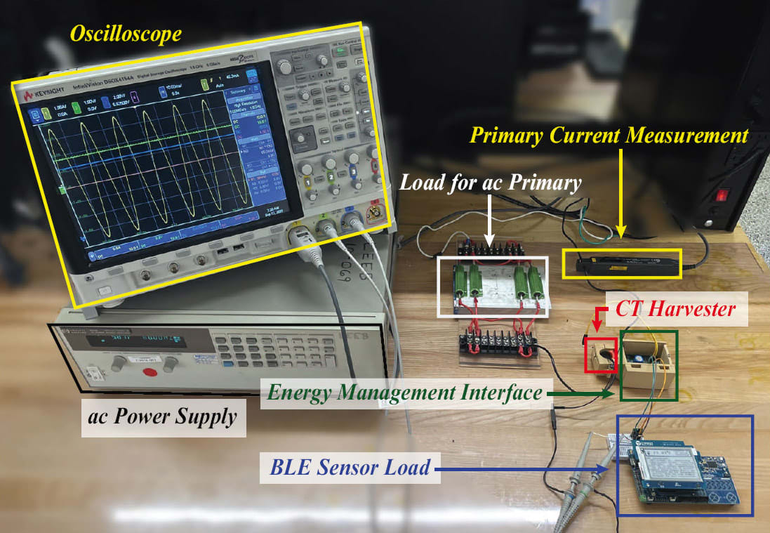
There are three parts to the system:
There’s the harvester itself, which is the transformer scavenging energy from magnetic fields in the system.
There’s the end sensor — the actual thing you use to get information from the environment.
There’s the energy manager — the circuit in the middle that interfaces the harvester to the sensor.
The energy manager, the circuit in the middle, is the focus of our work.
The energy manager takes as an input, the harvester. It delivers power at its output to the sensor node, but in the middle, it’s got supercapacitors for energy storage. Since supercapacitors are very energy-dense, we can pack a lot of energy into a relatively small volume.
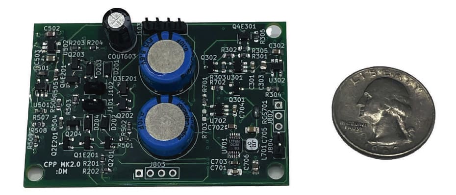
We also have discrete integrated circuits on the energy manager circuit board, which monitor the level of stored energy in the system. They’re looking at voltages and currents, seeing how well the power harvester is doing — whether there is enough energy to enable the sensor to start taking measurements.
Tech Briefs: How does your circuit manage a cold start-up of the system?
Monagle: If you simply hook up an energy harvester to a sensor, the energy you’re harvesting will likely start the sensor before there is enough energy to keep it going. The sensor will turn on, then off, over and over.

So, we use what we call glue logic. We have a comparator circuit that looks at the voltage on our energy storage capacitors to determine if we have enough voltage, enough energy, to start up the system. The actual energy management circuitry won’t start operating until there is enough stored energy to keep it going. To accomplish this, we use a commercially available comparator chip with what’s called a power on reset feature. With that, even when there’s very little voltage, or very little or no power, anything beyond a few microwatts or nanowatts, the existing logic states of our energy manager will be held constant until the input voltage reaches the required level and enables the system to boot up.
Tech Briefs: How does the energy manager work once it’s been triggered on?
Monagle: We then use maximum power point tracking (MPPT), which means that the energy manager adjusts the electrical load on the harvester to maximize the amount of harvested power from the environment.”
Tech Briefs: How does that work?
Monagle: Our harvester has an AC output, which we rectify into DC to store in our supercapacitors. When we start up with zero energy stored in the supercapacitors, the glue logic is in control, and the rectification is done with an uncontrolled Schottkey diode full wave bridge.
However, each Schottky diode is paralleled by a MOSFET, which serves as a controllable rectifier. Once there is enough energy, the glue logic hands over control and coordination of the energy flow to the MCU, which starts actively driving the gates of each MOSFET to control the flow of energy for maximum power point transfer.
Maximum power point tracking depends on the type of harvester. In our case, we use a split core transformer clamped around a current-carrying conductor. It harvests relatively large amounts of energy compared to some of the other energy harvester technologies.
There are all sorts of factors, we have to account for to achieve MPPT: The current in the primary, the voltage on the secondary, the current coming out of the secondary, and the timing of the current coming out of the secondary — when it’s happening along the course of the sinusoid. These all relate to how much power flows into the supercapacitors on the energy manager, how much power we’re harvesting.
Our MCU measures the voltage and average current flowing out of the energy harvester every 120 Hertz. It then adjusts the timing of when the harvester dumps current into the capacitors in order to change the power.
Leeb: If you think about the harvester for a second, if you didn’t know any better, it looks like a simple transformer. The primary of the transformer is driven by the current in a conductor going to some load. The secondary is connected to the electronics of the sensor that we’re interested in powering. However, if it was that simple, there wouldn’t be much to talk about.
Upon a closer look, it’s not that simple. The transformer input is determined by the load it’s powering, perhaps a motor. Its secondary voltage is chosen based on the needs of the sensor we want to use. And those two things are more or less fixed. With those two constraints, you want to operate everything else you have control over so that you get as much power as possible for your sensor.
With our system, a reasonably sized core is going to saturate. The reason is that you’re exposing the transformer secondary to the fixed voltage of the electronics that are operating the sensor.
To achieve maximum power transfer, we control the point during the AC cycle at which the transformer starts conducting. If you start harvesting power at the beginning of the cycle, you’ll saturate after a certain amount of time. But you started at zero, so by the time the transformer saturates and stops powering the sensor you will not have had the most input power you could have. The sweet spot is to start conducting when the primary current is near its peak.
One way to think about it is you have a finite window of time when you can draw power before the transformer saturates. You want it to saturate because if it doesn’t, it means you aren’t getting everything you could. You were running with too low a secondary voltage and weren’t getting as much power as you could.
So, what you want to do is center the time when you’re drawing power so that it’s at the peak of the primary current. You’ve got the fixed secondary voltage and the peak primary current, which winds up giving you the maximum power — that’s the maximum power point. The method Dan uses to determine the best point on the cycle is to perturb it and move it around until you get to the window where if you moved in either direction you’d be getting less power.
Tech Briefs: How does your system deal with variations in the primary current?
Monagle: One of the really nice things about the specific MPPT implementation that we use is that even when the primary current changes, the perturb and observe method maximizes the power that’s actually coming out of the harvester. So, our technique enables the sensor to be powered for a whole range of inputs.
Tech Briefs: Can this same approach be used with different kinds of harvesting sources?
Monagle: The same general design principles apply, but the underlying hardware implementation is where you see things start to change. So, for example, if we went with a solar cell harvester instead of our current transformer, we wouldn’t need a rectifier because the output of a solar cell is DC. Also, the technique for achieving MPPT would have to change. We’d still use an algorithm to maximize the power out of the harvester source, but it would be a different one.
Tech Briefs: What do you see as next steps in the development of this technology?
Monagle: We want to make it smaller so that it can fit in tight places like inside a motor terminal box. But beyond that we want to take advantage of AI tools to design techniques for minimizing the energy used by the system.
This article was written by Ed Brown, editor of Sensing Technology. For more information, contact Daniel Monagle at