
A turbine manufacturer wanted to get more power out of hundreds of turbines that were originally built and installed in the 1950s. The basic idea was to use the original outer casing but upgrade the internal components such as the blades and diaphragm. All of the components of the turbine needed to be reverse-engineered so that computer aided design (CAD) models could be created and used as the basis to analyze and optimize the turbine design. The parts ranged from small components to the case, which is 11 feet long, 6 feet wide, and 8 feet tall, and weighs 30,000 pounds.

Instead, the turbine manufacturer contacted NVision’s Engineering Service Division. Using a non-contact 3D optical scanner called the MAXOS and a HandHeld 3D portable scanner, NVision’s technicians were able to completely reverse-engineer the turbine in only six weeks at a substantially lower cost than the turbine manufacturer had budgeted for the project. The resulting CAD geometry was used to perform a computational fluid dynamics (CFD) simulation whose results helped dramatically improve the performance of the turbine. The geometry was also used as the basis for designing the new internal components of the turbine. Measuring the critical blade geometry to high levels of accuracy made it possible for the turbine manufacturer to perform simulations that helped to redesign the blades and diaphragms to substantially improve the energy efficiency of the hundreds of existing turbines.
CFD technology gives engineers the opportunity to understand how flow affects the performance of turbine blades and quickly and inexpensively evaluate alternative geometries by determining their impact on energy efficiency. In order to run CFD simulation it’s essential to have a CAD model that accurately depicts the as-built turbine geometry. The problem is, nearly all of the turbines that are prime candidates for Steam turbine interior components. design upgrades were designed without a CAD model, so reverse engineering is an essential first step to improving the turbine blade design.
Size Matters

The alternative would have been to use a CMM, which has a probe that must physically touch the part. The primary limitations of a CMM are that the operator must manually move the steering system to track each point to be measured and the device can only capture one point at a time. But to accurately model the geometry of a complex 3D contour, like those found on many turbine parts, you need millions of points, sometimes many millions, to get the geometry exactly right.
Generating this number of points with a CMM would take months, as the most that can be captured in a week is probably somewhere in the tens of thousands. Of course, it is possible to intelligently select and capture only the most critical areas, but you are often left approximating contours and can never be totally sure that you aren’t missing important points. Like a CMM, the MAXOS follows a pre-programmed path, but the MAXOS can capture cross-sections at a rate of 100 points per second, many times faster than a CMM. Another problem with the CMM is that there is no way to determine the angle at which the contact probe is contacting the surface of the part under measurement. This leads to a phenomenon known as cosine error in which the measurement is off by the cosine of the probe radius.
Point of Light
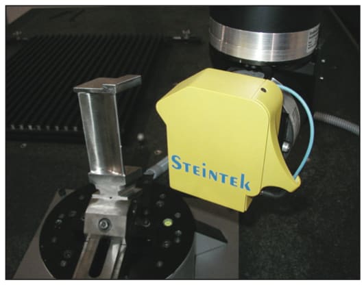
The MAXOS makes measurements with a single point of concentrated light rather than a touch probe. The light is measured using triangulation by a camera like a conventional laser scanner. However, the MAXOS provides higher accuracy than any laser scanner and provides accurate measurements on shiny surfaces because it reads the very center of the point of light. The MAXOS can inspect turbine blades without having to apply a matt coating like other non-contact scanning systems, which introduces dimensional inaccuracy.
The NVision HandHeld scanner, used in this case to inspect the larger components, is a portable device that is capable of capturing 3D geometry from components of virtually any size. It is attached to a mechanical arm that moves about the object, freeing the user to capture data rapidly and with a high degree of resolution. An optional tripod provides complete portability in the field. Intuitive software allows full model editing, polygon reduction, and data output to all standard 3D packages.
The technicians visited the OEM’s site and scanned millions of critical points in only three weeks. They scanned all of the turbine components including the case, inlet chamber, blades, rotors and diaphragm using the NVision Hand-Held scanner and touch probe. They scanned the smaller blades up to 12" in size using the MAXOS non-contact measurement system.

This article was written by Colin Ellis, Engineering Manager, NVision, Inc. (Coppell, TX). For more information, contact Mr. Ellis at