
The concept of dense wavelength division multiplexing (DWDM) in fiber optic communication networks gained traction when optical amplifiers became available. Able to amplify an entire wavelength grid at once, they removed the need to first demultiplex, then convert every channel to an electrical signal, regenerate it, convert it back to an optical signal, and finally multiplex all channels onto a single optical fiber.
 Tunable transmitters offered relief to maintenance groups and manufacturing planners dealing with up to 80 different flavors of transmitters: a single transmitter type, programmable to the required channel wavelength at the time of installation, was sufficient to form a DWDM transmission system. Moreover, it could be reprogrammed later — a first step towards reconfigurable add-drop multiplexers.
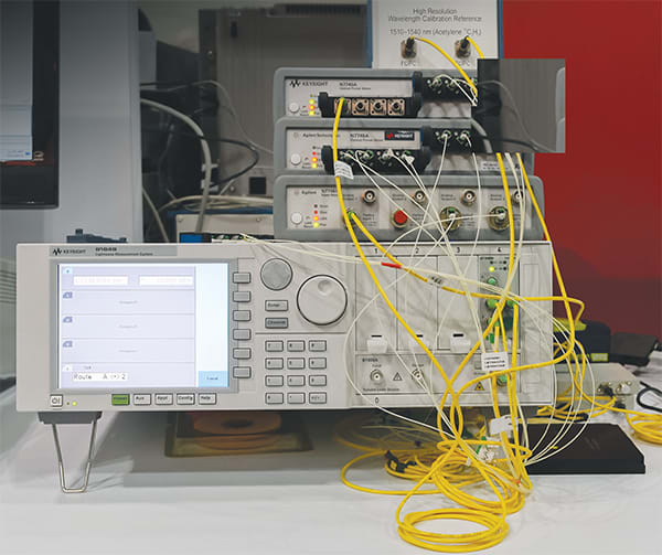
Tunable laser sources for test and measurement use came into high demand at the massive deployment of DWDM transmission systems. Every multiplexer and demultiplexer had to be validated for its crosstalk isolation, channel wavelengths, bandwidths, uniformity, and polarization dependence. Soon, these tests became limiting to the production capacity of optical component manufacturers, until the first sweeping tunable lasers boosted production capacity far enough to satisfy the telecom industry’s hunger for bandwidth.
Combined with multiple power meters, such lasers test all de-multiplexer ports at a time in one wavelength sweep. If required, a polarization controller adds the capability to measure polarization dependent loss, wavelength, and TE/TM mode shift of planar devices.
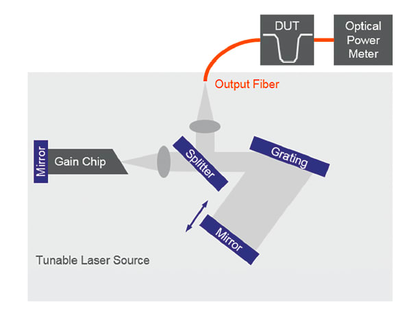
Well, tunable lasers for test and measurement purposes follow different optimization criteria than tunable transmitter lasers. Let’s take a quick look at the generic tunable laser design shown in Figure 1.
Like every laser, tunable lasers consist of a gain medium and a resonator, most often an external cavity. They are tuned by changing the cavity’s resonance condition. Our example shows the widely used Littman-Metcalf configuration*, where the resonator length and the diffraction angle of the grating are tuned by rotating the mirror around the Pivot point such that there are no phase jumps in the resulting output light. A fraction of the optical power leaves the cavity through a beam splitter and is collimated into an optical fiber which connects to the device under test (DUT).
Like TTLs, most tunable lasers are equipped with polarization maintaining fiber (PMF) that ensures a well-defined state of polarization. A keyed optical connector and PMF come in handy with open beam setups and planar device tests. An optical power meter completes the test setup. Any deterministic wavelength dependency in the optical path is removed by normalizing against a reference measurement without the DUT. This requires good power and wavelength repeatability while sweeping.
The sweep range is influenced by a tunable laser’s ability to maintain a laser mode across a wide wavelength range without allowing a different laser mode to come up — an effect called “mode hop.” Mode hops during a sweep appear in the form of a discontinuity in wavelength and optical power. They can render a measurement unusable, because mode hops are sporadic, and not repeatable. For an efficient test method, wavelength sweeping has to be both fast and accurate. Measurement times of a few seconds and wavelength uncertainties of less than five picometers are state-of-the-art.
A number of well-documented laser cavity designs are used by test equipment designers that theoretically enable mode pulling over a wide distance, to the limits determined by dispersive elements in the cavity; namely the gain medium and collimator lenses. The laser’s mode pulling capability will then reflect how precisely the mechanical alignment was done during the instrument assembly. Also, mechanical tolerances, vibrations, and acoustic resonances inject variations to the wavelength-over-time profile, and to the velocity-over-wavelength profile. While additional actors in the cavity can compensate for tolerances and vibrations, they add cost and complexity to the instrument design as they need to be precisely controlled during the sweep.
How wide a tunable laser can sweep is also limited by the bandwidth of the gain medium: commercially available tunable lasers reach a tuning range in the neighborhood of 200 nm, equivalent to 13% of their center wavelength.
Swept-wavelength measurements of multiport devices like DWDM de-multiplexers rely on synchronously triggered power meters. The accuracy of the wavelength scale depends on the precision of the trigger with respect to the tunable laser’s actual wavelength. A proven concept to achieve highly accurate measurements is to take wavelength samples synchronously to the power meter samples while the laser sweeps. Most vendors offer detectors that provide a real-time wavelength reading.
- Karen Liu and Michael G. Littman, "Novel geometry for single-mode scanning of tunable lasers," Opt. Lett. 6, 117-118 (1981), doi: 10.1364/OL.6.000117
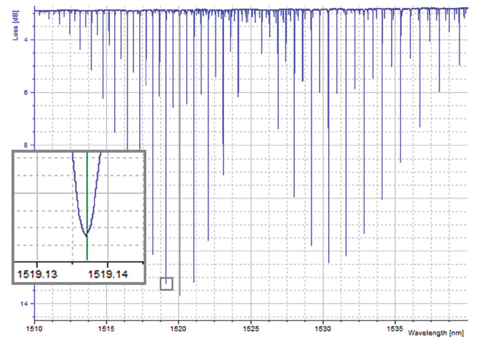
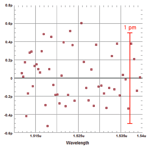
In Figure 3, we compare the measured center wavelength of 12C2H2 absorption lines with their known values, according to NIST SRM 2517a. The measurement was acquired at 200 nm/s sweep speed with a Keysight 81606A tunable laser and an N7744A optical power meter. The result is repeatable and mostly independent from the chosen sweep speed and sweep direction. This tunable laser has been designed for optimal sweep linearity and operates under closed-loop wavelength control.
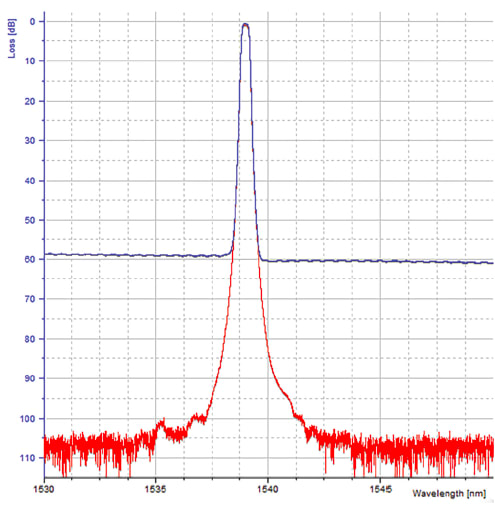
The amount of source spontaneous emission (SSE) of a tunable laser is another property of its cavity design. SSE is spectrally broad incoherent light and represents energy that escapes the resonance condition, thus reducing the laser cavity’s selectivity. Tunable lasers for measurement applications must have enough optical output power to compensate for losses in the test setup, and a good signal-to-SSE ratio to enable the evaluation of optical filters with low crosstalk or good stop band isolation.
Selectivity can be increased by additional tunable filters inside the cavity — filters that block undesired laser modes and spectral noise — or by cavity designs that let the laser light pass the optical grating multiple times per roundtrip. Generally, operating the gain chip at high electrical current ensures there is more energy concentrated in the desired laser mode and relatively less energy in the spontaneous emission. Limiting factors include the power dissipation of the gain medium and its impact on the thermal stability of the laser, as well as accelerated aging when the laser current gets close to the operating limits.
While the use of tunable transmitter lasers for optical component measurements is appealing due to their high optical power, low cost, and small form factor, they fall short in several important disciplines. Tuning beyond the limits of the DWDM grid is rarely supported yet required to ensure filter shapes are good at the edge of the grid. Highly accurate swept-wavelength measurements spanning the entire DWDM grid, and essential for effective high-resolution testing, are not available from today’s TTLs. Finally, tunable transmitters have SSE levels that prevent exploring the stop band isolation of optical band pass filters and notch filters. Widely and accurately sweeping external cavity lasers satisfy all these requirements, and reach a measurement accuracy level close to that of benchtop wavelength meters.
This article was written by Stefan Loeffler, Product Planner, Digital & Photonic Test Division, Keysight Technologies, Inc. (formerly Agilent Technologies electronic measurement business), Santa Rosa, CA. For more information, contact Mr. Loeffler at