
As any dolphin could tell us, sound travels well in water. While water absorbs electromagnetic radiation and light waves over relatively short distances, sound travels widely and even faster in water than in air. That’s why we use sonar (SOund NAvigation Ranging), the acoustic equivalent of radar, to detect and locate underwater objects.
Sonar system developers continually seek to increase performance while also reducing size, weight, and cost, but this is easier said than done. Factors that must be taken into account include the characteristics of acoustic-wave propagation in water of varying densities, the vibrations and elastic waves that come into play with respect to the sonar system’s materials and components, electrical considerations, and many others.
Building and testing a series of physical prototypes on a trial-and-error basis is one way to conduct system development, but this tedious approach is time-consuming, costly, and makes it difficult to achieve real-world performance close to the theoretical best case.
In contrast, the use of tightly coupled multiphysics modeling, simulation, and visualization capabilities, such as those provided by the COMSOL software environment, can speed up system development exponentially and lead to a better end result as well.
A case in point is the development of a new type of sonar acoustic projector, designed to provide improved performance at half the size and weight of existing projectors. Stephen Butler, an Acoustical Engineer and Principal Investigator at the U.S. Navy’s Naval Undersea Warfare Center Division Newport in Newport, RI ( www.navsea.navy.mil/nuwc/newport/ default.aspx ), used COMSOL Multiphysics with the Acoustics Module to accelerate the development of the new projector.
The Naval Undersea Warfare Center Division Newport provides research, development, test and evaluation, engineering, analysis and assessment, and fleet support capabilities for submarines, autonomous underwater systems, and offensive and defensive undersea weapon systems. The Center also stewards existing and emerging technologies in support of undersea warfare.
Sonar Basics
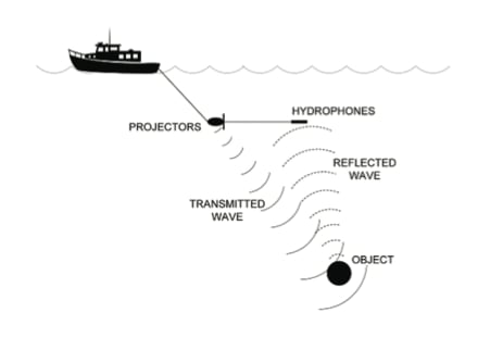
A sonar system consists of a projector to transmit acoustic energy and an array of hydrophones to receive the reflected sound waves from underwater objects. Sound waves are not generally unidirectional, though, so one key design goal is to increase the strength of the acoustic beam in one direction and to null it in the other. This will result in a more precise acoustic beam, which increases the sonar system’s capability to detect objects (Figure 1).
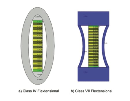
Some acoustic projectors are based on flextensional transducer technology. These are rugged, high-power, and compact devices, with an actuator such as a piezoelectric ceramic stack positioned between curved metal shells or staves made from aluminum, steel, or fiberglass. The staves may be either convex or concave, but are usually convex in conventional devices (Figure 2). The actuator is fixed to each end of the curved shells so that as it expands and contracts with an applied electric field, that motion is converted into flexure of the shells with an approximately 3:1 amplification in motion. These flexures produce acoustic energy in a manner similar to that of an acoustic loudspeaker’s cone.
Butler used COMSOL to perform multiple computer analyses, which allowed data manipulation to determine the effects of all possible design variables. The software was key to his ability to calculate the complex AC voltage drive coefficients required to drive the transducer into the directional mode.
Creating Directional Beams
A flextensional transducer is physically small compared to the acoustic wavelength produced, and thus its acoustic output tends to radiate omnidirectionally. This is undesirable in some sonar applications. A common method used to generate a directional beam with a null in one direction (a cardioid beam pattern) is to employ multiple transducer elements spaced one-quarter of a wavelength apart. However, the use of multiple elements creates diffraction effects that limit the directionality of the acoustic output, or the front-to-back pressure ratio, to a modest 6 dB. They also increase the sonar system’s size and weight.
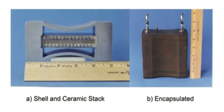
Butler was able to improve on conventional technology by using COMSOL Multiphysics to accelerate the development of a new class of device known as a directional “dogbone” (Class VII) transducer. It generates highly directional beams from a single element instead of from an array of elements, thus reducing diffraction, size, and weight. The word “dogbone” refers to the shape of the device, which uses two concave shells, or beam-radiating surfaces (Figure 3).
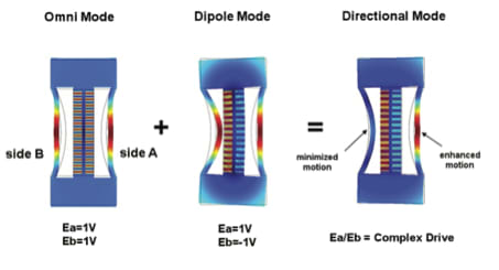
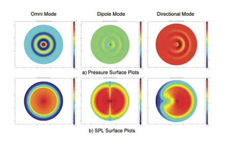
Key to the new device is its piezoelectric ceramic stack, which has two active sections separated by an inactive section along its major axis. Driving both sides of the stack in-phase allows the shell to be driven in conventional mode, which creates an omnidirectional radiation pattern. However, a dipole radiation pattern is created when the two sides are driven 180 degrees out-of-phase with one another, because the stack bends in response to the applied electric field and excites an asymmetric mode in the shell.
By combining the omnidirectional and dipole modes through the use of appropriate AC drive voltage coefficients, the acoustic pressure output can be doubled in one direction and nulled in the other direction, resulting in a highly directional cardioid beam pattern. These complex drive coefficients would have been difficult to determine without advanced, tightly coupled multiphysics modeling and simulation capabilities (Figures 4 and 5).
As a result, the new directional dogbone flextensional transducer can generate a unidirectional cardioid radiation pattern with a front-to-back ratio greater than 20 dB at the null, independent of operating frequency. Moreover, this cardioid pattern is developed over an octave frequency band, meaning it operates over a wide bandwidth and thus is more versatile and useful in generating waveforms than conventional flextensional transducers.
COMSOL’s Acoustics Module was used because it includes structural, acoustics, and piezoelectric elements. It is tightly coupled with the company’s overall multiphysics software environment such that one can easily construct a structural computer model, determine its modal harmonic content, and predict its directional performance.
The Making of a New Transducer
The first step in developing the new transducer was to create a one-dimensional equivalent-circuit model of it to characterize its resonance modes. Equivalent circuit models are simple representations of an electromechanical device that include its material properties. They consist of an arrangement of simple electrical components: inductors, capacitors, and resistors.
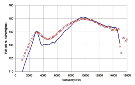
In the equivalent-circuit model, voltage would represent a force, electrical current would represent a velocity, inductance would represent a mass, and capacitance would represent a spring. Once the equivalent-circuit model had satisfactory results, it was refined by the software to create improved two- and three-dimensional structural computer models. The computer models were validated by comparing them to actual in-air and in-water data obtained by physically measuring the resonances of an experimental Class VII omnidirectional-mode dogbone flextensional transducer.
The validation of the software modeling was a multi-step process. First, the modeled piezoelectric ceramic stack characteristics were compared with the physical stack. Then, the modeled shell modes of vibration were compared with the physical shell. Finally, the modeled stack with the shell was compared with the physical integrated unit.
The results of these modeled vs. measured data comparisons were so close, it gave full confidence in the ability to use simulation to establish a baseline to predict the real-world performance of the directional dogbone device to be built (Figure 6).
Both far-field acoustic pressures of the omnidirectional and dipole modes were predicted and, in turn, these were used to determine the complex drive coefficients required to drive the transducer into the directional mode.
Also, the model of the piezoelectric stack could be divided into two active halves, enabling the impedance of each side of the stack to be independently determined. This made it easier to understand how to drive each half, and thereby to derive the proper AC voltage drive coefficients for each half.
This understanding would have been extraordinarily difficult to obtain otherwise. COMSOL’s coupled-acoustic modeling capability was essential to get the “null” value for the back of the device, because it enabled Butler to get the in-fluid acoustic pressures and the in-fluid phase values individually. Without the ability to do that, it wouldn’t have been possible to derive the drive coefficients.
Major Improvement
In today’s world of undersea warfare, the threats and the necessary responses to them are getting more difficult, important, and urgent. Sonar is a key element of national defense, and modern sonar development efforts benefit greatly from powerful modeling, simulation, and visualization capabilities.
This article is based on S.C. Butler’s “A Directional Dogbone Flextensional Sonar Transducer,” COMSOL Conference Proceedings, Boston, October 2010. Visit www.comsol.com/papers/7916/ to view the full presentation.