
With the standardization of 4G wireless, the increase in cloud storage and computing, and the push for faster network data rates, the highest quality passive interconnect systems must be used. While the robustness and size of these interconnections, fiber types, and cable management all play major roles in the backbone, what happens at the tip of the connector also greatly affects the optical performance of the system.
With cable preparation, it’s important that the fiber is not damaged during stripping. Fiber chips will cause optical loss. While the connector is installed, the proper amount of epoxy and the correct cure schedule is critical. Too much epoxy and the spring will lock up; too little and voids will form. If the correct temperature isn’t met for the proper amount of time, the epoxy will not fully cure. In both cases, the longevity of the connector will be marginalized.
After cable preparation, connector installation and crimping, and epoxy curing, the end face needs to be processed. The steps include cleaving (also called scribe and break) and polishing. Cleaving and polishing bring the connector to the required specifications. A flaw in any of these steps may cause a yield problem. These steps also have an impact on the steps that follow, and may contribute to problems further down the termination process.
Standard polishing for single fiber connectors typically consists of three to five polishing steps, starting with relatively rough epoxy removal grit and gradually going to a final lapping film, which can be .02 um. Some of the middle steps use relatively costly diamond films, which are used multiple times to minimize the CoC (“Cost of Consumables”) per connector.
The Challenge
The industry is continually looking for ways to increase yield, decrease CoC and labor expense. Reducing the number of polishing steps helps. CoC goes down, yield goes up, labor cost goes down, and less equipment and equipment maintenance are required. There is a clear way to get there.
Traditionally, cleaving is done using a scribe tool with a sapphire, ruby or carbide tip. A careful operator has to scribe the fiber just above the cured epoxy and gently pull the tip of the fiber parallel to the fiber axis without producing a crack. When not done properly, this resulting crack often makes the termination. This operator has to be one of the more careful and conscientious people in the factory, and does the same repetitive job all shift. If a crack does result from the scribing procedure, the connector needs to be cut off and the entire process needs to be redone. On breakout cables with many fibers, this creates other problems. If breakouts are at precise lengths, all ends would need to be redone.

Before connectors are terminated, when they are purchased, they come in with the correct geometry, radius of curvature, and apex offset. With traditional manual cleaving, the connector end face is being destroyed during the epoxy removal step and has to be reformed.
The Solution
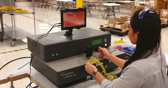
A new cleaving technique, using a CO2 laser, largely automates the process. The operator simply places the connector into the laser cleaver, the laser scans across the fiber and epoxy bead, and it cleaves both together. The human factor is eliminated from the cleaving and denubbing steps.


Note: In a production environment, there may be a requirement to perform a very brief silicon carbide polishing step to remove the epoxy residue before the final film. This also helps extend the life of the final film.
Next Steps
Most 2.5 mm ferrules used by assembly manufacturers are preprocessed with an ROC of 15 to 25 mm. This ROC reduces the polishing time after traditional hand cleaving. This ROC range is too wide for many terminated connectors. The ROC distribution of incoming ferrules is too wide for the needed finished termination. With 1.25 mm ferrules, the situation is slightly different. Many assembly manufacturers use incoming ferrules with flat pedestals, as opposed to pre-radiused. To take full advantage of laser cleaving and minimize polishing as much as possible, it may help to specify incoming ferrules within the mid-range of the final connector spec, and with tighter tolerance.
A successful relationship between two companies, Fiber Optic Center (FOC) and Sagitta Engineering Solutions Ltd., has defined a business process of specialization and expertise. Sagitta’s expertise is in laser manufacturing and automation. FOC, on the other hand, specializes in working with cable assembly houses by consulting on and providing all the equipment and supplies needed for making up cable assemblies. They do not, however, sell cable assemblies. FOC and Sagitta work hand-in-hand with each assembly house to figure out what, if any, changes are needed on incoming parts, as well as the implementation of the technology.
FOC’s technical experts travel to manufacturing sites, set up the laser system, and develop the most cost effective process while achieving optimum technical results. They look at the entire process, from cable preparation to testing, to make sure all stations are operating at the highest level. Once they have the process, the technical expert helps to integrate the system into the line and stays with the operators until they are completely comfortable using it. In the highly competitive world of fiber optic cable assembly, it is important to stay ahead with the best equipment and processes, and new techniques in laser cleaving can help achieve this.
This article was written by Daniel (Didi) Hachnochi, CEO, Sagitta Engineering Solutions Ltd. (Simpsonville, SC) and Ben Waite, Executive Vice President, Fiber Optic Center (New Bedford, MA). For more information, contact Mr. Hachnochi at