
New technology combines the benefits of non-contact linear position sensing with the programmability of a programmable controller in a relatively small sensor package. This technology can help engineers in applications including those where costs and/or development time can be saved with all necessary control functions handled by the position sensor, applications requiring high accuracy over a small distance, and applications with high vibration or noisy environments. Practical applications include material handling equipment, crimping machines, and position sensors for linear actuators.
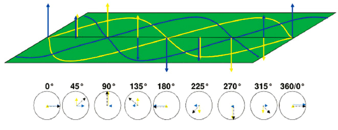
Adding these two fields together results in the formula:
H•sin(x)•cos(wt)+H•cos(x)•sin(wt) = H•sin(wt+x)
where x is the position of the magnetic pickup or marker, t is time, w is the frequency of the waveform applied, and H is the strength of the magnetic field. It shows that the phase of the sum of the magnetic fields (wt+x) at a distinct measurement point is directly proportional to the linear position x. By measuring the phase shift between the outgoing and the received sinusoidal signals, a dc voltage is produced that is proportional to the phase difference or phase shift caused by the position marker’s change in position.
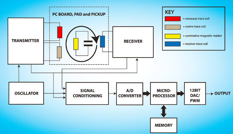
By using an inductive measurement technique, the same microprocessorbased circuitry is leveraged to add programmable features to a position sensor. Accessing the microprocessor for programming is accomplished using momentary switches and indicators. A current realization of this technology on a product uses two buttons that double as LEDs to provide both input and programming feedback in a small area on the sensor housing.
Several useful parameters can be programmed including electrical measurement range, slope, position for minimum output voltage/current, position for maximum output voltage/current, and offset. By setting the min and max range points at values other than zero and full scale, slopes other than 1:1 are possible, including negative slopes.
In high noise environments, maximum noise rejection can be achieved by applying the entire output range to the actual travel length required by the application, rather than a longer full stroke length of a position sensor. By programming an offset, a sensor can be adjusted for deviations or tolerances in mounting the physical sensor without moving it. Separately, output voltage can be set to either a minimum or maximum threshold within its range. If the full-scale range is 0 to 10 V and the operating range is set to limit the output to 1 to 9 V, an output falling outside the imposed limits would serve as a fault detector, indicating a likely open or shorted cable.
This article was contributed by Ivan Masek of Novotechnik and Mark Hersum of AAI. For more information, Click Here .