
The figure depicts an improved apparatus for three- or four-point bending tests of stripe specimens. In a bending test, the specimen is subjected to tension along its top surface and compression along its bottom surface, or vice versa. A three- or four-point bending fixture of older design is capable of pushing from one side only, so that it can bend the specimen in one direction only; that is, it can induce either tension or compression (but not both) on the top or bottom surface. The present apparatus is capable of pushing on a specimen from either side and thus bending the specimen in either direction. Thus, for example, the apparatus can be used to perform a test in which the applied stress is varied continuously from a maximum tension through zero to a maximum compression.
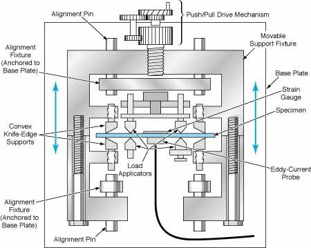
The Specimen Can Be Bent Up, Down, or Both during a test in this four-point bending apparatus.
The specimen is placed between two pairs (for a four-point test) or one pair (for a three-point test) of knife-edge load applicators that are anchored on a base plate. One load applicator is fixed; the other three are adjustable. Pairs of convex knife-edge supports on a movable support fixture are also positioned in gentle contact (while in the zero-applied-stress condition) with the specimen near the ends of the specimen.
A manual push/pull drive mechanism translates the movable support fixture up or down to exert a compressive or tensile stress on the upper or lower surface of the specimen. Alignment pins ensure that the stress is applied perpendicularly to the nominal longitudinal axis of the specimen. A strain gauge is attached to one side of the specimen and an eddy-current probe (or other sensor) to the other side. During the bending test, the eddy-current signal is recorded as a function of the strain. The eddy-current signal as a function of stress and/or strain yields information on residual stress in the specimen. Optionally, the apparatus could be automated by motorizing the drive mechanism and using the output of the strain gauge as a feedback control signal for the motor.
This work was done by E. James Chern of Goddard Space Flight Center. No further documentation is available. GSC-13801