
In the field of technical imaging, the term “trigger” is often used synonymously with the term frame-synchronization (or f-sync) signal. In the scientific high-speed imaging world, these terms are distinctively different. This confusion originates from the fact that industrial machine cameras and scientific high-speed cameras have, for the most part, existed as two separate communities.
In the machine vision sector, a trigger signal generally corresponds to an input voltage edge that initiates the “capture of a frame.” But in the high-speed imaging sector, a trigger is the near-instantaneous moment when the camera halts its first-in first-out (FIFO) process. This process involves a continuous recording of frames into the RAM at the set frame rate, where new frames enter at the same rate at which the oldest frames exit. The moment of triggering (a single voltage edge) is considered “time zero,” and the next frame thereafter is frame zero.
In the high-speed industry, “trigger” and “trigger position”:
- Mark the moment in time when frame zero is defined — known as the “trigger frame.”
- Define the ratio and total number of post- and pre-trigger frames.
- Are initiated by serial commands from software or by hardware signals via BNC connection.
- Can directly link to an experimental test rig for timing precision, fidelity and reproducibility.
- Could initiate from a change in sound, pressure, light, pixel value, voltage, temperature, etc.
The ability to set a “middle trigger” is powerful when the event of interest is short and unpredictable. It enables the camera to capture an ultrafast or ultrashort event with both pre- and post-trigger frames with seconds of record time and ensures that key information is recorded.
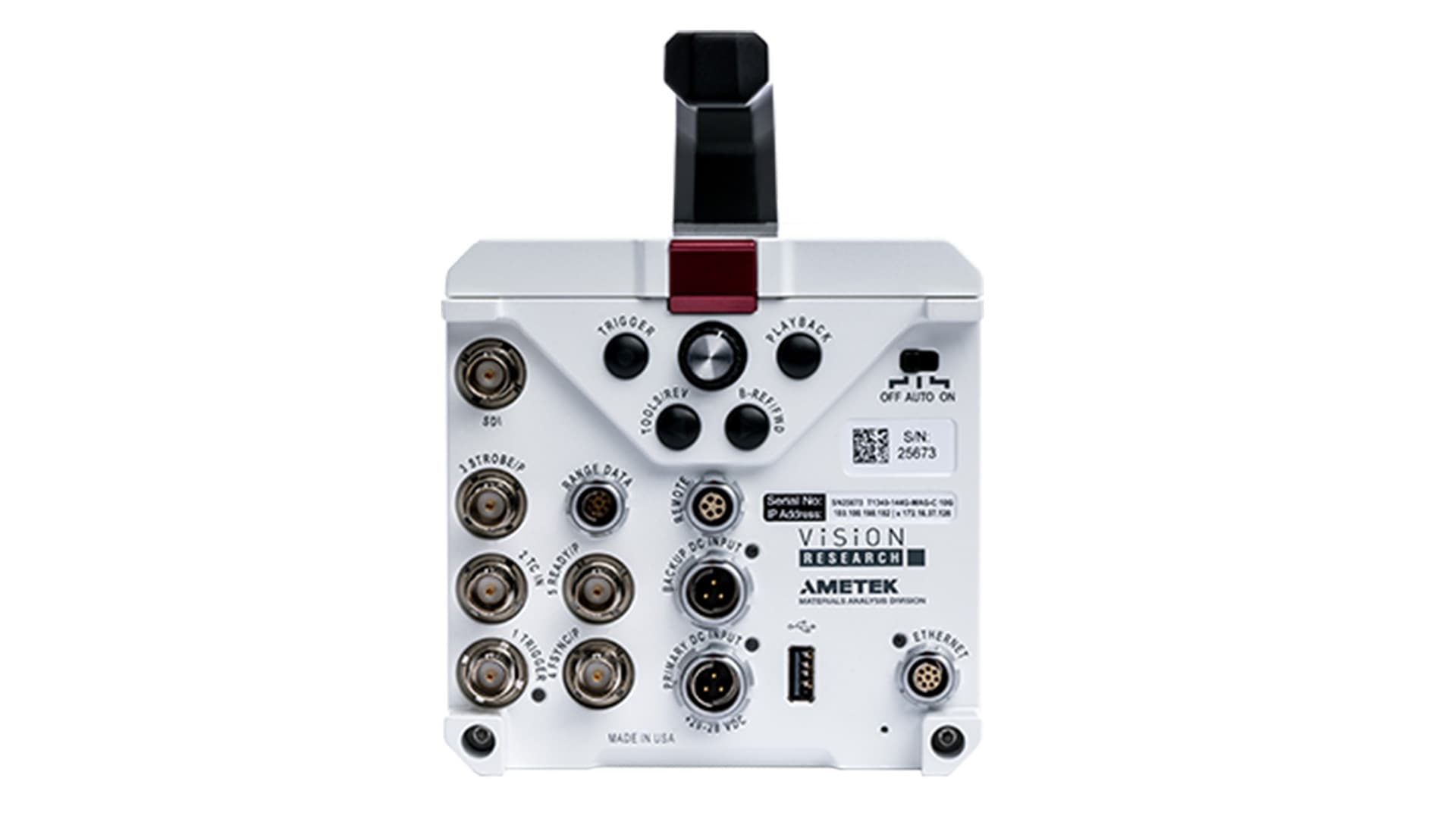
To make trigger setup easy, all Phantom cameras feature a dedicated rear panel or breakout box on BNC labeled “TRIGGER.” The breakout box is a component on the Phantom camera. And if you require additional trigger inputs, cameras that feature programmable I/O ports can have one or more triggers assigned as an “Aux Trigger In” port. Determining an optimal triggering strategy ensures you will capture potentially unpredictable, high-speed events with precision, all while using minimal resources.
Let’s look at the six triggering methods that Phantom cameras support:
1. Contact Closure and Opening Switch. The contact closure (and/or opening switch method) involves shorting (and/or opening) a BNC cable’s center pin to the ground to trigger the camera. When performed, the trigger signal of the BNC either falls from 5 V to 0 V or rises from 0 V to 5 V. The camera will then trigger on either the falling edge when the short occurs, or on the rising edge when the short is removed after the circuit is opened to let the trigger input rise back to 5 V. The user can configure rising or falling edge mode in the camera’s control software.

This triggering method is easy to set up with simple components like switches, relays and break wires. The Phantom “pickle switch” is a popular handheld device used to apply a trigger with this method. The contact closure and opening switch methods can also be used over cable distances of several kilometers as long as the line resistance doesn’t reduce the voltage below the threshold, which depends on the camera model, but generally is around 2.5 V.
Compared to the software-based method, the hardware trigger method is required for triggering synchronized cameras to ensure each camera receives a trigger signal at the same exact moment in time. Thus, this is the preferred method for triggering connected cameras. Software triggering is not viable because software commands are sent serially, and thus a phase shift will occur in the frame number between cameras.

Ideally, these cameras should also be f-synced together, which is a method to use the camera’s clock pulses to signal the camera to store an image into its memory buffer. F-syncing ensures there are no phase differences among the system of cameras. It is also worth noting that a timecode sync should also be used to ensure timestamp matching among synced Phantom cameras.
2. Transistor-Transistor Logic (TTL) Trigger. This method is similar to the contact closure method because the camera can be set to trigger on the rising or falling edge of a TTL pulse. It’s also good for synchronized cameras. However, accommodating large distances can be a challenge depending on the circuit design.
This method supports the use of third-party devices for DSLR camera shutter releasing and flashing. Devices include the MIOPS multi-trigger, Pocket Wizard wireless remote or a function and pulse generator. Like the contact closure method, this instantaneous trigger method delivers aligned frame numbers, provided all cameras are connected to the same trigger source.
3. DC Voltage Trigger. This method triggers the camera according to a DC voltage rising above or falling below a threshold of 7.5 VDC. The DC voltage applied must be between 7.5 and 30 to be effective. This technique aligns all frame numbers and is good for systems that produce a signal that exceeds standard TTL voltages. While this is an instantaneous trigger method, a slight delay may still occur between the time the threshold is met and when the voltages are applied or removed. Keep in mind that if input voltages exceed 32 VDC, damage to the system may occur.

4. Software Trigger. A simple software trigger uses a Phantom camera control (PCC) or custom SDK-based interface (SDK = software development kit). An SDK interface, for example, is a command interface built from MATLAB, Python, LabVIEW, and/or C++/C#. Other than the Ethernet connection to the PC, this method requires no hardware or cabling. Software triggering is never recommended for triggering a system of synchronized cameras because the trigger command will be received by each camera sequentially, and in order of their connection, causing a delay and misaligning the frame numbers as a result.
5. Image-Based Auto Trigger (IBAT). The image-based method can automatically trigger the camera when motion is detected in the field of view (FOV) of the camera. Registered “motion” depends on user-defined pixel intensity change, a check-up interval, and an area-percentage the subject must occupy within a user-drawn box. This trigger method is key for when a user’s event of interest occurs at a completely random time and/or cannot be captured using hardware or software methods. Examples include events occurring in vacuum chambers or enclosed vessels. It’s important to note that when the camera detects motion it also immediately outputs what is called a “IBAT signal”, which is simply a change in voltage. In some cases, this particular feature in the Phantom camera is used purely as a motion detector to trigger even faster data collection systems.
6. On-Camera Controls. Some Phantom cameras feature a physical trigger button on the rear panel which is useful when working with a single camera in a remote setup or without a software connection. This method should not be used in synchronized applications or applications that must avoid camera shake. Because it is virtually physically impossible to press multiple buttons simultaneously and close their switches at the exact same instant, triggers will be initiated at different times and their frame numbers will not align.
This article was written by Gene Nepomuceno, Field Applications Engineer and Kyle Gilroy, Applications Development Manager, Vision Research (Wayne, NJ). For more information, visit www.phantomhighspeed.com .