Over the last few years, there has been a dramatic increase in the number of satellites in orbit. A significant portion of this increase is thanks to the smaller size of newer satellites. Although the largest orbiting structure, the International Space Station, is larger than a football field, most of the satellites in orbit today are much closer in size to a football. This is in part due to the popularity of the CubeSat form factor, with a so-called 1U satellite fitting within a 10 cm x 10 cm x 10 cm envelope. The small size makes it possible to launch multiple satellites from a single rocket. Although originally envisioned for mostly academic purposes, there is now a robust commercial ecosystem providing design solutions ranging from 1U to 24U — and the use of CubeSats is growing at a remarkable rate.
One of the characteristics of the CubeSat designs (and other small satellite designs) is that they are very compact. Many miniaturized cameras, sensors, instruments, antennas, batteries, attitude control systems, and other electronics are closely packed and can generate waste heat. Designing the satellite to properly radiate this heat to surrounding space is one of the primary engineering concerns. Engineers must ensure that the various electronic components stay within certain temperature ranges, but this can be challenging, as thermal gradients can lead to undesirable structural deformations. Since it is quite difficult to do any kind of truly realistic preflight testing, the design process has to rely heavily on numerical modeling.
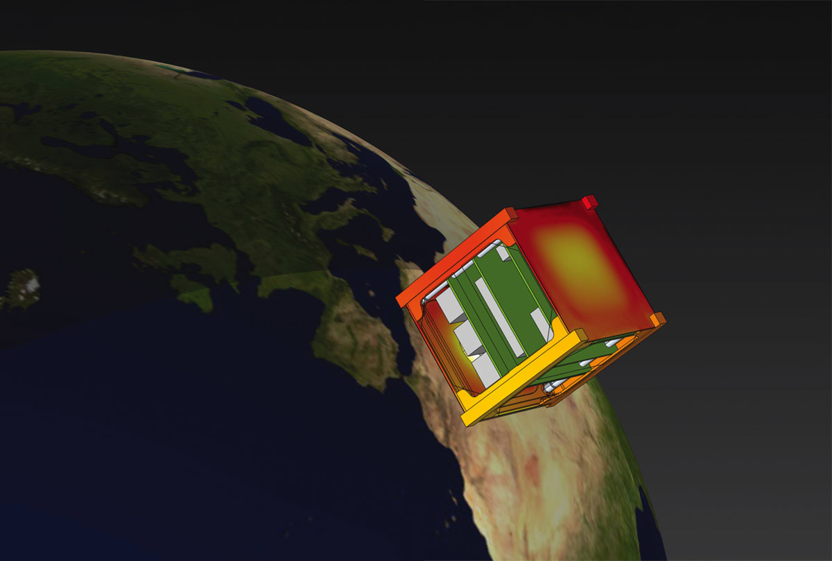
Once the satellite is in orbit, it might be tempting to think that the numerical model is no longer needed, but this is not true. Components will fail, often for unknown reasons, and the remaining electronics may need to be driven in unanticipated combinations. The satellite operator still needs the thermal model to predict behavior in such circumstances, with the objective of increasing operational lifetime (Figure 1).
Working with Numerical Models
All numerical models involve solving an approximation of the governing equations describing heat transfer. They can range from being very simple models to nearly full-fidelity models that include many of the geometrical and physical aspects. The most simplistic numerical model would reduce the geometric complexity of the satellite structure and only compute, in a lumped sense, a single temperature over time for the satellite. From there, one could work toward introducing temperature variations across various subsystems or components of the satellite. This would require the numerical analyst to introduce many approximations, assumptions, and separate calculations into their model.
On the other hand, a full-fidelity model is based directly on the CAD design and takes the opposite approach. By starting directly with the CAD design, much of the tedious manual validation and verification of each simplification that goes into a reduced model is obviated. Of course, working directly with the CAD is going to lead to a greater computational cost: a CAD-based numerical model will subdivide the geometry of the satellite into thousands, or even millions, of different computational elements, so there is a tradeoff.
Historically speaking, the lumped modeling approach had a lot going for it. Computers used to be relatively slow, so having the numerical analyst spend time semimanually reducing the computational complexity was important for getting results quickly. This approach is still relevant for the modeling of very large structures like the International Space Station, but for small satellites — especially as computational costs continue to drop — it is now becoming increasingly attractive to start at the other end of the modeling spectrum.
In practice, a thermal analyst will want to work somewhere on the spectrum between a wholly simplified and a full-fidelity model. For example, it might be desirable to replace the CAD description of each screw and fastener with a lumped thermal resistance at the surface between the joined components. Similarly, it might make sense to reduce an electronic component such as a chip or battery to a block of material with averaged properties and internal dissipation.
Important Modeling Considerations
Regardless of the modeling approach taken certain aspects, as described below, need to be considered.

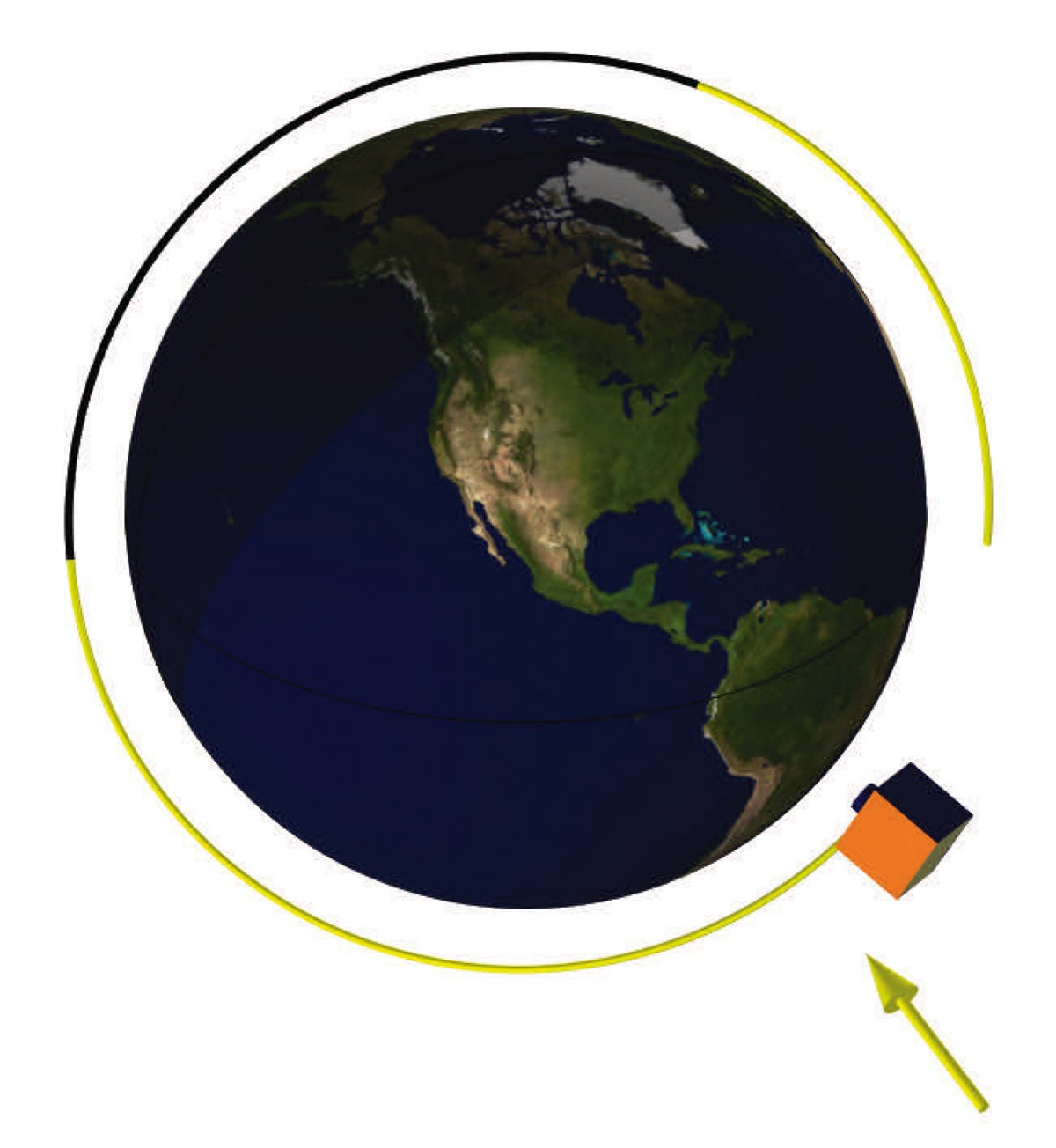
The geometric description of the satellite. The CAD design and thermal properties (thermal conductivity, density, and specific heat) of the materials being used in each component determine the total thermal mass of the satellite as well as the conductive heat transfer between parts. The relative orientation of the satellite faces also determines the view factors, describing how well one surface can see another surface. This is needed when computing radiative heat transfer. Along with the CAD design, there is additional information that is related to the geometry. For example, the mating surfaces between two parts might have a thin coating, or a bonding material, that alters the thermal contact resistance. The total resistance can also be a function of contact pressure, as determined by the mounting hardware (Figure 2).
The emissivities of all exposed surfaces. Emissivity (or absorptivity) is a measure of how well a surface emits and absorbs thermal radiation. It can be a function of wavelength, temperature, and angle of incidence. The combination of the view factors and surface emissivities is used to compute the radiative heat exchange. There is radiation both on the exterior surfaces of the satellite and within the interior. The exterior surfaces also experience environmental heat loads, such as the thermal irradiations from the Sun and Earth. It is particularly worth understanding the topic of wavelength-dependent emissivities. The Sun is the primary source of heating and the only source of electrical energy, via solar cells. The light from the Sun is classified as short-wavelength light, with peak intensity at the 500-nm wavelength and with most energy in the sub-5-μm wavelength range. The satellite itself is much colder than the Sun and emits thermal radiation at much longer wavelengths, primarily at wavelengths greater than 2 μm. Because of this, it is very common to use thermal coatings that are strongly wavelength dependent. A coating with low emissivity at shorter wavelengths will reduce solar heating, but if that same coating has higher emissivity at longer wavelengths, it will radiate heat more effectively.
The satellite orbit. Defined by the standard Keplerian orbital elements, the satellite orbit determines how the satellite travels around the Earth and when it goes into and out of eclipse. When the satellite goes into eclipse, there is no longer any solar irradiation, which usually leads to significant drops in temperature on the exterior surfaces. For thermal modeling purposes, the orbit itself can typically be treated as periodic, especially in the context of small satellites in low Earth orbits.
The satellite orientation. This information determines which faces see the Sun, the Earth, or deep space. The satellite may be pointing in a particular direction, spinning about its axes, or even have parts of the structure that are rotating and moving relative to the satellite frame. This information affects the irradiation onto the exposed faces. The orientation, unlike the orbit, might not be periodic. For example, a satellite antenna might be pointed toward a ground station only every few orbits.
The radiative properties of the Earth and Sun. The solar flux varies throughout the year, and this solar flux is both directly incident on the satellite and also diffusely reflected from the Earth. The magnitude of this reflection, known as the albedo, can vary over the planet surface. The Earth itself is also a radiator of infrared light, and this radiated flux can be a function of latitude and longitude. Although solar flux is well known, the albedo and Earth infrared radiation also vary significantly over the planet’s surface and over time.
The electrical dissipations of the components. The solar cells convert incident light into electrical energy, which is used to charge the batteries that drive the electronics. These various electronics all dissipate heat while in operation, and these components may be on continuously, on at specific predetermined times, or switched on in response to specific conditions. For example, a heater can be controlled by a thermostat to hold a component within a desired temperature range.

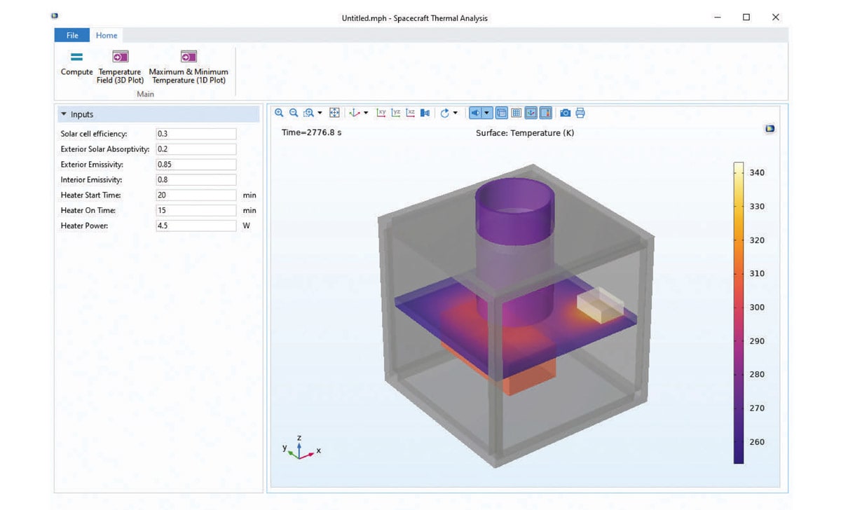
Accounting for all of these elements while modeling requires the use of efficient and reliable multiphysics simulation software, such as COMSOL Multiphysics ® (Figure 3).
Satellite Modeling in COMSOL®
The Heat Transfer Module, an add-on to COMSOL Multiphysics®, includes a dedicated user interface for satellite modeling: the Orbital Thermal Loads interface. Based on a hybrid finite-element–radiosity method, the functionality of this interface enables engineers to use a CAD-centric approach to build near-full-fidelity models of small satellites. The interface is seamlessly integrated into the COMSOL product suite and offers a simple way to define material properties, loads, and boundary conditions; extract results; and define physics couplings for multiphysics simulations. The Heat Transfer Module also has functionality for modeling fluids, phase change materials, heaters, and thermoelectric effects, as well as for lumped system modeling.
The Orbital Thermal Loads interface provides a convenient way to define and verify the orbit and orientation, as well as Sun and planet properties. From there, it computes the solar, albedo, and Earth infrared irradiation using a two-band radiation model, with a user-selectable division between the solar (short-wavelength) and ambient (long-wavelength) bands. This allows for specifying different emissivity in different wavelength bands. A single-band model additionally provides a simplified approach. If an even higher level of detail is needed, it is possible to use a multiband radiation model.
COMSOL® can either read in vendor-neutral CAD formats or be bidirectionally linked with popular CAD packages, such that any changes to the CAD model will be instantaneously updated in the numerical model. This CAD geometry can be cleaned up using defeaturing tools or simplified for meshing using native functionality. Alternatively, it is also possible to create geometries within the software.
Computing the Results

Once all this information is assembled and put into a thermal numerical model, the computed results will show the temperature variation over time. For a very simplified model, this might just be a bulk temperature. For a higher-fidelity model, the spatial temperature variation within all components is computed (Figure 4). This information can be used to check if the satellite will stay within all operational thermal limits. From there, the analyst may want to move on to other types of analyses, such as computing structural deformations that happen due to thermal gradients to see how such deformations alter the optical performance of a telescope. This kind of extensive numerical modeling reduces the need for physical testing and can make satellite engineers confident in their designs prior to launch.
Since the solar, albedo, and Earth infrared irradiation can be considered nearly periodic between orbits, the total irradiation over one orbit can be computed prior to the thermal transient calculation, which typically spans several orbits. This order of operations makes it simpler to test what-if scenarios, such as different combinations of surface emissivities. When iterating through designs, it is possible to use the Batch Sweep capabilities on large single computers or the Cluster Sweep node capabilities on cluster and cloud computing resources.

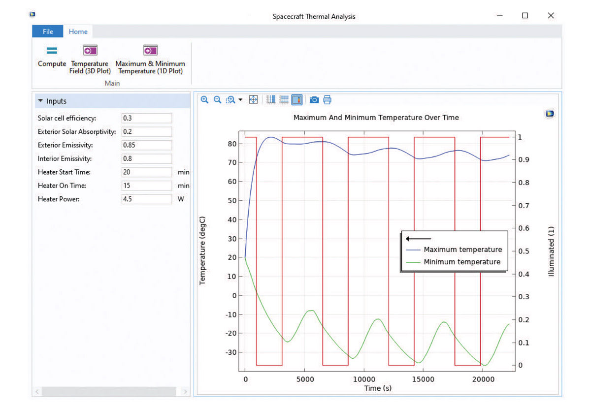
Once the design iterations are complete and the satellite is ready for delivery, the COMSOL numerical model can be packaged as a standalone application and given to the satellite operator so that they can test unexpected operating conditions as needed (Figure 5).
Conclusion
Thermal management of satellites is a complex design task, and the operational environment is hard to replicate in physical tests. For instance, there are variables that can only be foreseen with the use of simulation, such as the temperature variations that may occur as satellites travel through orbit or the heat generated by onboard equipment. With COMSOL Multiphysics®, engineers can quickly iterate and improve designs, verify operational conditions, and share their numerical models with coworkers and customers as simulation applications.
COMSOL and COMSOL Multiphysics are registered trademarks of COMSOL AB.
This article was written by Walter Frei, Principal Applications Engineer, COMSOL, Inc. (Burlington, MA). For more information, visit here .

