
Aspheric lenses let optical system designers improve resolution, reduce the number of lens elements required, and increase system light throughput. Their complex, non-spherical surfaces correct for more spherical and higher-order aberrations than the spherical surfaces of conventional lenses. However, aspheres often have steeper surface angles than spherical lenses, which introduces unique challenges while depositing optical coatings.
The coating effects caused by steep aspheric surfaces may increase unwanted reflections and shift the spectral performance of the lenses. However, careful attention to coating materials and deposition parameters can minimize these effects. Understanding the impact of lens steepness on coating performance can help optical system designers choose the proper coatings for their application.
Why Would Aspheres be Steeper than Other Lenses?
The answer is quite simple: because you can while still maintaining high performance. There is a direct relationship between a lens’ f/# and its diffraction-limited spot size, meaning that smaller focused spot sizes can be theoretically achieved if the lens has a smaller f/# or larger numerical aperture. However, in practice, decreasing f/# to improve diffraction-limited resolution introduces greater spherical aberrations, which end up decreasing resolution. Therefore, traditional spherical lenses have to make a tradeoff between minimizing diffraction-limited resolution and minimizing aberrations.
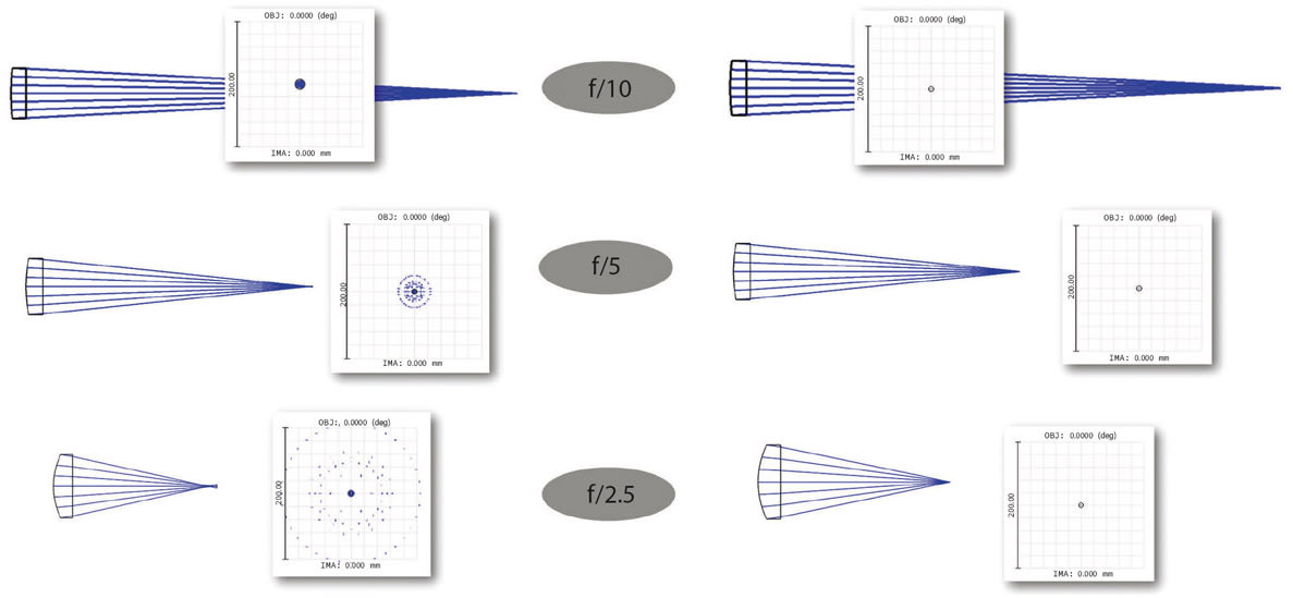
The complex surfaces of aspheric lenses correct for spherical aberrations, allowing them to reduce f/# while still focusing light to a diffraction-limited spot. Figure 1 illustrates this in an example. The images on the left show spherical lenses moving to smaller f/#'s. While their diffraction-limited spot size is decreasing, the actual spot size achieved increases because of greater spherical aberrations being introduced. However, the images on the right show that aspheres at the same f/#'s are able to maintain diffraction-limited performance, leading to even smaller spot sizes. This improves system performance, but the steepness of the actual lens surfaces increases in order to focus light at sharper angles. This is why aspheres often have steeper surfaces than spherical lenses. One thing to note is that Figure 1 shows some spot sizes smaller than the diffraction limit because this simulation is based on geometrical ray tracing and is not using physical optics propagation. The actual focused spot size will, of course, not be smaller than the diffraction limit.
Impact of Surface Slope on Coating
Two main challenges are introduced because of steep aspheric surfaces: the deposition effect and the angle-of-incidence (AOI) effect.
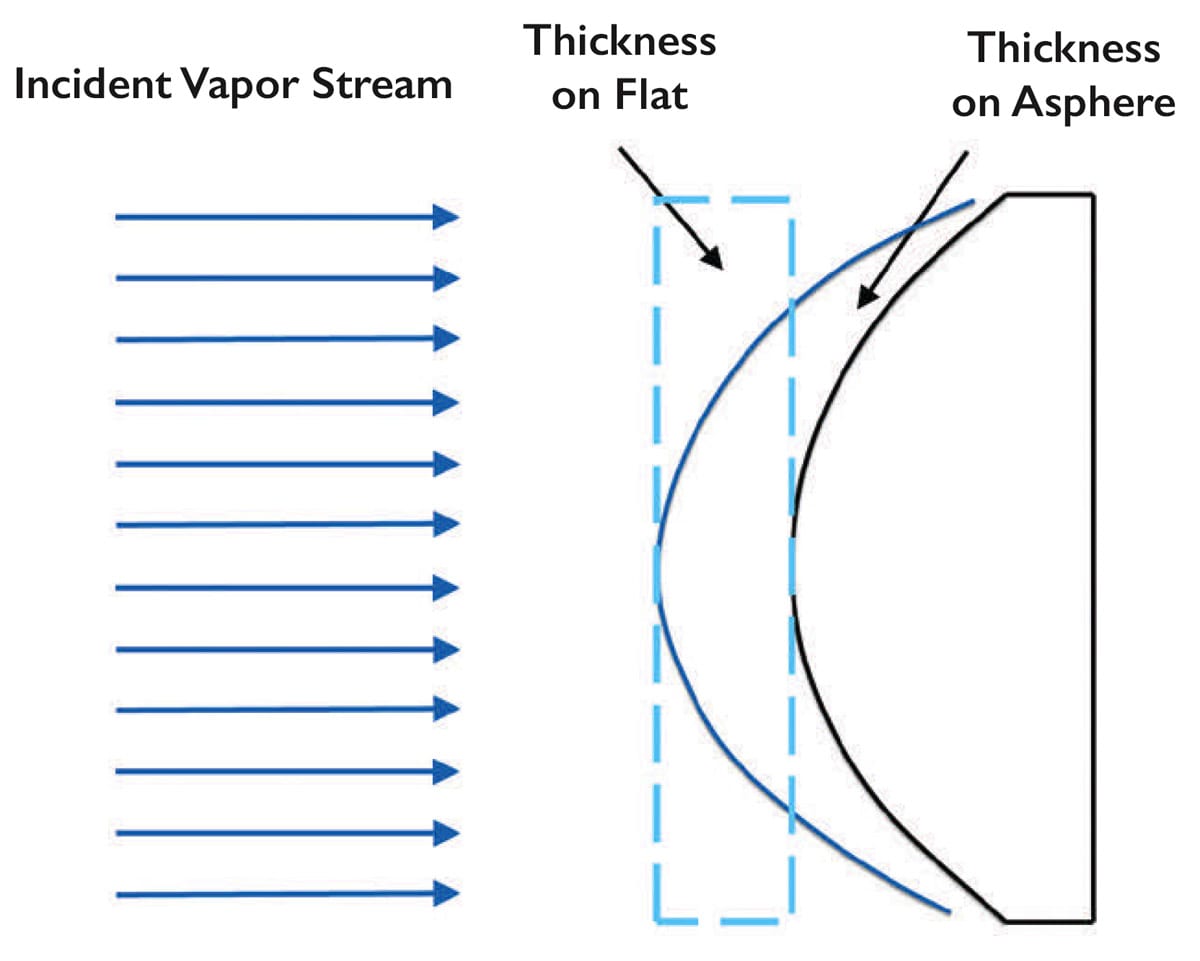
The deposition effect is an issue that occurs inside the coating chamber that has to do with the optic's geometry. It causes the thickness of the deposited coating to vary with lens diameter. As the vapor stream of depositing atoms arrives on an optic, if the optic were flat the coating would have a flat, uniform thickness (Figure 2). However, since the area of a curved surface is larger than that of a flat surface with the same diameter, the conservation of mass demands that the coating become thinner towards the edges of the surface. The thickness in the center will be the same as the thickness on a flat surface. The steeper the curved surfaces of a lens, the more pronounced the deposition effect will be. The thinner the coating, the more the spectral performance is shifted to longer wavelengths, leading to different spectral performance at the lens edges versus the center.
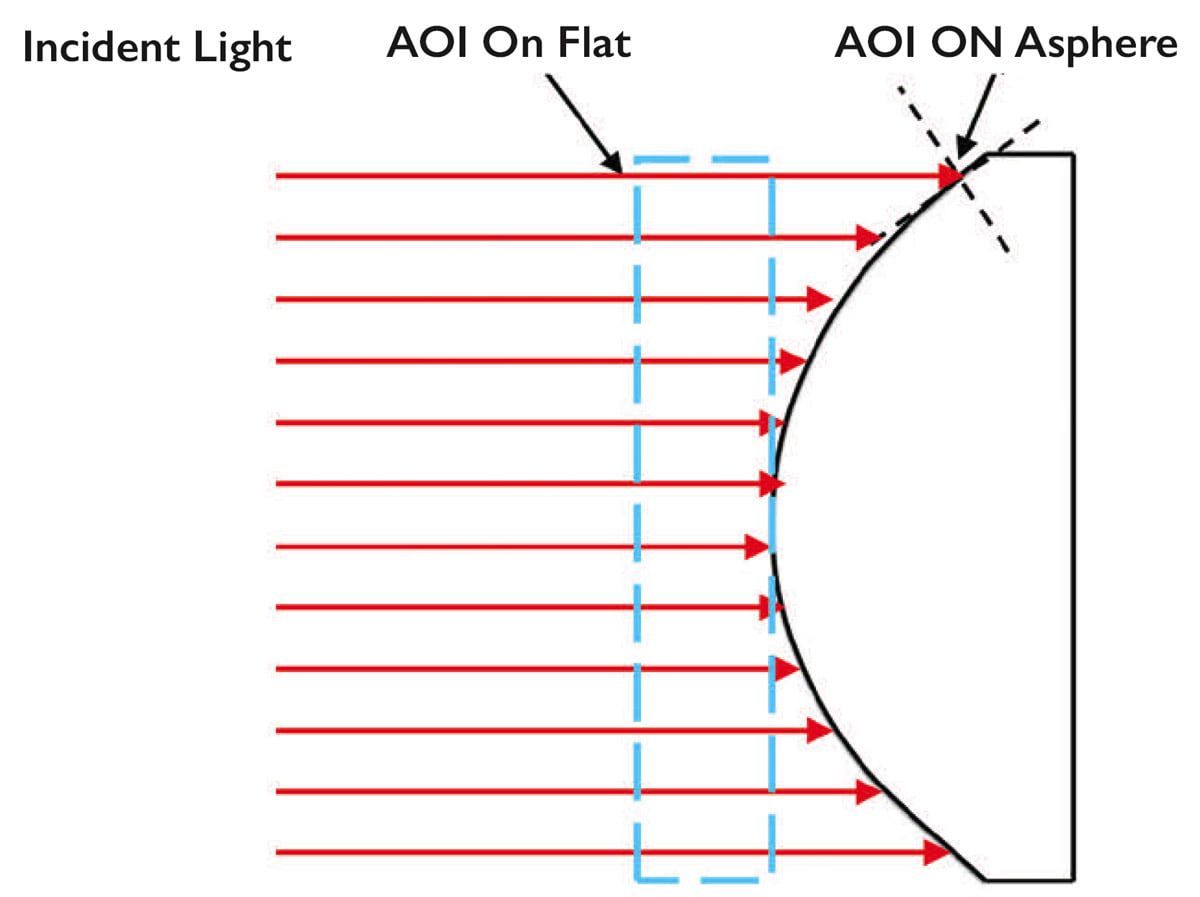
The AOI effect occurs in the end application, and is demonstrated in Figure 3, where collimated rays incident on a lens experience larger angles of incidence toward the edges compared to the center of the lens. Again, this effect is more pronounced for lenses with steeper surfaces. Clearly, both the deposition effect and AOI effect impact performance as a function of diameter, as rays at the edges of the lens will be incident at both higher angles and onto thinner regions of the coating. To simplify this discussion, we will ignore the convolution of these two effects and evaluate them separately. The larger incident angles at the edges of the lens also cause a shift in spectral performance to longer wavelengths.
How these Effects Change Lens Performance
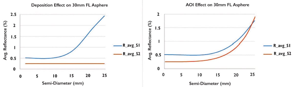
It was stated earlier that the deposition and AOI effects shift spectral performance to longer wavelengths, but they can also lead to unwanted reflections, which reduces lens throughput in the desired wavelength range. As an example, these effects will be analyzed for a plano-convex asphere with a 50 mm diameter, 30 mm focal length, simple MgF2 (magnesium fluoride) coating on the curved surface, and an N-SF6 substrate. The angle of incidence of the rays striking and leaving the lens can be calculated through optical design software like Zemax OpticStudio if the lens prescription is known. Figure 4 shows increases in unwanted reflections as a function of the lens’ semi-diameter. In the plots, “S1” is the aspheric surface while “S2” is the planar surface. Average reflections are shown for the wavelength range of 425 – 625 nm. For semi-diameters around 0 - 12.5 mm, which corresponds to angles of incidence of approximately 0 - 30°, there are minimal impacts from both the deposition and AOI effects. However, at larger semi-diameters, and therefore steeper angles, average reflectance increases significantly, which leads to losses in lens throughput. Both the deposition and AOI effects impact performance quite noticeably, with the exception of the non-existent deposition effect on the flat side of the lens (“R_ avg_S2” on the left of Figure 4). Note that beyond 12.5 mm the deposition effect causes reflection to increase even more sharply than the AOI effect.
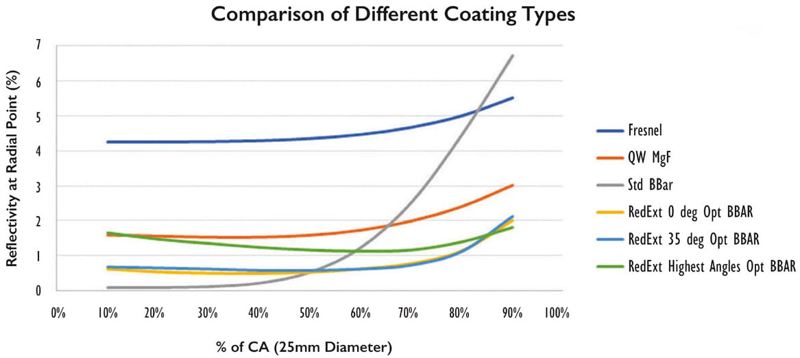
Different coating designs are impacted by the deposition and AOI effects differently. Figure 5 compares how different types of coatings from Edmund Optics® are affected. An interesting finding is that some coatings that perform better at low angles of incidence are more sensitive to angle and have sharp increases in unwanted reflections at higher semi-diameters. For example, the coating titled “Std BBAR”, representing Standard Broadband Anti-Reflection, has very low reflectivity when only a small percentage of the lens clear aperture (CA) is used, but reflectivity sharply increases closer to the edges of the lens. Because of this, a coating that may initially not seem like it would provide higher transmission, like MgF2, may be a better option.
There is no one-size-fits-all approach for selecting the best coatings or optical components. Coating and lens manufacturers can manipulate many different parameters to balance the different specifications of your lenses. Speak to your optical manufacturer for guidance on what lens geometries and coating types can get you both the resolution and coating performance needed for your application.
This article was written by Cory Boone, Lead Technical Marketing Engineer; Chris Cook, Technical Fellow, Thin Film Development; and Amy Frantz, Design Engineer; Edmund Optics® (Barrington, NJ). For more information, visit here .