
CubeSats provide the ability to conduct relatively inexpensive space missions. Over the past several years, technology and launch opportunities for CubeSats have exploded, enabling a wide variety of missions. However, as instruments become more complex and CubeSats travel deeper into space, data communication rates become an issue as highlighted by a recent NASA centennial challenge proposal. A Ka-band highgain antenna would provide a ≈100× increase of data communication rates over an S-band high-gain antenna, and a ≈10,000× increase over an X-band patch antenna of the same input power, enabling high-rate data communication from deep space or the use of dataintensive instruments from low Earth orbit (LEO).
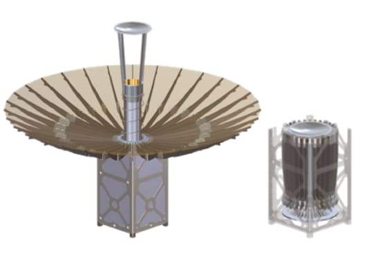
To design KaPDA, JPL first collaborated with USC/ISI to understand and characterize the ANEAS antenna flight spare. Characterization showed the antenna needed to be entirely redesigned for Ka-band operation, although the folding rib architecture could be maintained. A Cassegrainian dual reflector design with a smooth wall horn feed and telescoping waveguide was selected, instead of the prime focus single reflector that ANEAS utilized. To hold the surface accuracy required by Ka-band, the antenna was designed with deep ribs, precision hinges, and a denser, stiffer mesh. The ribs are deployed by cables, actuated by a slowly inflating bladder, and then latched into place. Using a bladder reduces the whiplash that occurs in many other antenna designs where strain energy or springs are used for deployment. The sub-reflector is supported by a composite structure that telescopes along the horn during a spring-powered deployment.
RF design and a complementary mechanical deployment mechanism design have been completed. The antenna is 0.5 meter in diameter and stows in 1.5U (10 × 10 × 15 cm3). RF simulations show that, after losses, the antenna will achieve over 42 dB gain, which is above 50% efficiency. At the time of writing, a prototype was under development and slated for completion in early 2015, and a flight-ready antenna was scheduled to be built by the end of 2015.
This work was done by Mark W. Thomson, Richard E. Hodges, Nacer E. Chahat, and Jonathan Sauder of Caltech; and Yahya Rahmat-Samii of the University of California, Los Angeles for NASA’s Jet Propulsion Laboratory.
In accordance with Public Law 96-517, the contractor has elected to retain title to this invention. Inquiries concerning rights for its commercial use should be addressed to:
Technology Transfer at JPL
JPL
Mail Stop 321-123
4800 Oak Grove Drive
Pasadena, CA 91109-8099
E-mail: This email address is being protected from spambots. You need JavaScript enabled to view it.
Refer to NPO-49503
This Brief includes a Technical Support Package (TSP).
Ka-Band Parabolic Deployable Antenna (KaPDA)
(reference NPO-49503) is currently available for download from the TSP library.
Don't have an account?
Overview
The document outlines the development of the Ka-Band Parabolic Deployable Antenna (KaPDA) designed for CubeSats, a project led by NASA's Jet Propulsion Laboratory (JPL) in collaboration with the University of Southern California/Information Sciences Institute (USC/ISI). The primary objective of the KaPDA project is to enhance data transmission capabilities for CubeSat missions beyond Low Earth Orbit (LEO) by enabling high-rate communications with the Deep Space Network (DSN).
The KaPDA is designed to stow within a compact 1.5U volume (10 x 10 x 15 cm³) and deploy to a diameter of 0.5 meters. This innovative antenna architecture utilizes an ANEAS mesh antenna, which underwent significant redesign based on characterization results. Key improvements included deeper ribs with precision hinges, thicker mesh requiring greater deployment force, and the incorporation of a sub-reflector, horn, and waveguide. The design aims to achieve a gain of 43 dB, significantly increasing data rates—up to 10,000 times greater than standard X-band patch antennas and 100 times greater than state-of-the-art S-band parabolic antennas.
The document details the deployment sequence of the KaPDA, where the hub is driven upward by inflation, deploying the root ribs and releasing the sub-reflector as the ribs open. The design challenge was to ensure precise deployment within 0.5 mm RMS, which is critical for the antenna's performance.
The project is positioned as a groundbreaking technology for future CubeSat missions, enabling advanced radar science missions and interplanetary communications, such as those exemplified by the MarCO and RaInCube missions. The document also references key publications related to the project, highlighting the contributions of various team members in mechanical design and RF engineering.
In summary, the KaPDA project represents a significant advancement in CubeSat technology, addressing the limitations of current communication systems and paving the way for more ambitious space exploration missions. The document serves as a technical support package, providing insights into the design, objectives, and potential applications of the KaPDA, while also offering contact information for further inquiries related to the technology transfer program at NASA.