
This technology is based on a model-scale experiment simulating a test facility where an engine exhaust is discharged into a duct. Such a configuration sometimes encounters unwanted noise in the form of high-amplitude spectral levels in certain frequency ranges or, in worst cases, a howl that can raise structural concern. The innovation involves placement of a velocity fluctuation damper at the end of the duct. Such a damper is shown to suppress not only the broadband unwanted noise, but also the howl when it occurs. Even though placing the damper on the upstream end of the duct works, the preferred location is the downstream end.
Previously, to alleviate the unwanted noise, various methods were used, such as water injection, “dragon teeth” (tabs), or a rod inserted perpendicular to the flow. These methods are ineffective, especially when the unwanted noise is simply due to the duct modes excited by broadband flow disturbances, manifested as broad peaks in the noise spectrum.
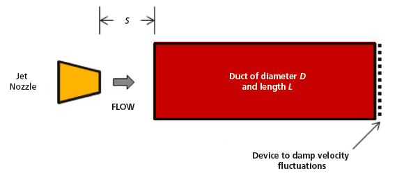
In the flow configuration, the jet discharges into the duct placed at a standoff distance, s. The duct can be of various cross-sectional shapes or it can be a diffuser. In Figure 1, the duct is a 1-in. (≈2.5- cm) diameter by 2-in. (≈5.1-cm) long cylindrical pipe placed in the path of a 0.58-in. (≈1.5-cm) diameter circular jet. The damper device is a 70-mesh screen with four ¼-in. (≈0.6-cm) diameter holes provided to alleviate flow blockage. In practice, the jet may be non-circular and the duct may be of other cross-sectional shapes. The duct may be connected to other duct sections and diffusers. The damper can be a screen covering the entire cross-section, but when alleviation of flow blockage is desired, open passages may be placed on the periphery near the duct wall. The damper could also be a simple obstruction in the form of a center body.
Figure 2 shows the noise suppression effect by the damper. Three pairs of sound pressure level spectra are shown for jet Mach numbers of 0.416, 0.747, and 1.087. In each pair, one spectrum (solid line) is without the damper when there is a loud tone represented by sharp spike(s) in the spectrum; the other spectrum (dashed line) is for the case with damper when the tone is eliminated by the damper.
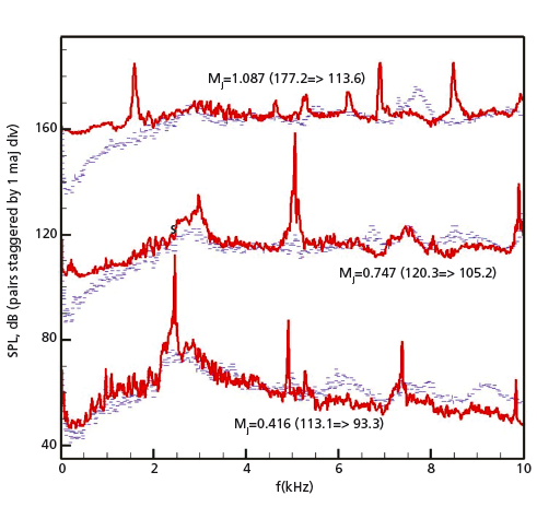
In the simplified model-scale geometry at low Mach number, the tone is generated due to a coupling of the jet “preferred mode” and the half-wave acoustic resonant frequencies of the duct. The damper location corresponds to the acoustic velocity anti-node (where the acoustic velocity fluctuation magnitude is the largest). By dampening the velocity fluctuation, the resonance condition is weakened, resulting in the noise suppression. At higher jet Mach numbers, the duct modes can be more complex, but the damper is still quite effective.
Figure 2 represents a case when there is a coupling, as described above, yielding a sharp tone (this corresponds to a howl in larger practical configuration). Often, the unwanted noise appears as a broad peak at the duct resonant frequencies when the dimensions of the jet and the duct are disparate and there is no coupling. The damper is found to be effective in suppressing such broad peaks that remain unaffected by other previously known suppression methods. The damper also works quite well when placed at the upstream end of the duct. This could be a suitable location in practice due to easy access. However, there is some penalty at high frequencies due to impingement of the high-velocity jet on the damper.
This work was done by Khairul Zaman, Michelle Clem, and Amy Fagan of Glenn Research Center. NASA invites and encourages companies to inquire about partnering opportunities. Contact NASA Glenn Research Center’s Technology Transfer Program at