Toyota Research Institute of North America (TRINA) has developed a simulation-driven generative design method and applied it to the design of flow field microchannel plates, which direct the movement of fluid reactants in microreactors like hydrogen — oxygen fuel cells. While much of Toyota’s fuel cell R&D is confidential, the TRINA team has published an article in Chemical Engineering Journal about their simulation-enabled “inverse design” process. Applying this process to flow field plates resulted in four distinctive microchannel designs ( Figure 1).

Each of the four designs has particular merits; all of them outperform existing benchmark designs in terms of key metrics. Just as important, they exemplify the power of process. TRINA has shown how generative design enabled by simulation can accelerate innovation. “We think that the inverse approach can revolutionize current design practice,” said Yuqing Zhou, a Research Scientist at TRINA.
A Reactant’s Path Through a Flow Field Plate
For as long as hydrogen and oxygen keep flowing, a fuel cell will keep generating electric current. Managing the distribution of these essential gases is the job of the cell’s flow field plates. Each plate includes both a microchannel structure and a porous sublayer. As hydrogen moves through the channels of the anode-side plate, it is also being forced through the sublayer toward the anode. Meanwhile, air is channeled through the flow field plate on the cathode side of the fuel cell. Air and water are exchanged through the cathode-side porous material layer, and the plate then channels excess air and water away from the cell stack. Figure 2 offers a simplified close-up of this essential process for the cathode side.

In their journal article, the TRINA team explained that “uniformity of fluid residence time or fluid flow distribution, and the relationship to optimal heat transfer, is directly related to the design of the flow structure, which is of primary importance for proper control of chemical reactions.” Accordingly, the two main objectives for fuel cell flow field plate design are to maximize fluid flow across the plate’s microchannel flow field and through the porous material layer, to supply sufficient reactant to the electrode.
A Simpler Process for Creating Complex Formal Solutions
The physical arrangement of microchannels helps determine how well a flow field plate meets its performance objectives. Historically, microchannel designs have followed a few familiar patterns. More complex forms could improve performance, but increasing a design’s complexity adds to the time needed to define, fabricate, test, and adjust that design.
Zhou and his colleagues recognized that before trying to optimize their designs, they first had to optimize their design process. To generate a higher-performing formal solution to their problem, the team created their simulation-driven inverse design methodology. Their methodology does not define forms in advance of testing, but rather sets key parameters and then directs algorithms to generate forms that fulfill those parameters.
“We were seeking an efficient way of approximating what a more complex simulation would show. We have sacrificed some modeling complexity, which actually enables us to explore more elaborate designs in less time,” Zhou said. “Some people use topology optimization for problems like this, and they come up with designs that maybe have 10 channels. This is because they are asking their algorithm to determine the exact placement of every physical element of the channels in advance, which requires a lot of computing power and time to achieve a complex design,” he explained.
From Desired Results to Novel Forms, Faster
So how could the TRINA team use its methodology to efficiently generate better microchannel designs? First, they simulated idealized flow trajectories through the effective anisotropic porous material, then they extracted values that described the idealized fluid behavior. Next, they input those values into another simulation, which generated the microchannel forms that would cause that behavior. Essentially, they defined the effect they wanted their designs to produce before designing anything.
Zhou explained, “Our COMSOL model of the porous material has only two material values and a very coarse mesh. We implement a sensitivity-based optimization process based on Navier-Stokes and advection-reaction-diffu-sion equations. We assume steady-state, incompressible, and laminar fluid flow through the porous media, and that the desired chemical reactions will occur proportionally to the reactant concentration. We run these simulations to arrive at an optimal distribution of fluid flow orientation through the pores. This process gives us valuable results with a huge reduction in computational complexity.”
Zhou describes this part of the overall design process as homogenization. Having now established a pattern of ideal trajectories of fluid through the plate’s pores, the next step is dehomogenization. This step involves the equation-driven definition of microchannel forms that will force fluid to follow these optimal paths.
Generated Designs That Maximize Flow, Reaction, or Both


The dehomogenization step is needed, Zhou said, because “we cannot fabricate an ideal porous material with each pore individually designed. We need to install walls and channels to direct fluid through the pores in ways that approximate the ideal. To generate this design, we use COMSOL Multiphysics® to solve a customized partial differential equation (PDE) for pattern generation. The software also gives us plotting functions we can use to visualize the results.”
Two of the formal options created by TRINA’s dehomogenization equations are shown in Figures 3 and 4. Their guiding performance objectives are to reduce resistance to reactant flow and to enhance reactant supply and reaction uniformity across the entire plate. These objectives are represented by governing variables in the model’s PDE. By assigning different weighting factors to these two objectives, Zhou and his team can induce the model to generate different design options. They can then evaluate the relative merits of each option and make adjustments to produce further iterations.
Of the design shown in Figure 3, Zhou said, “We call this the ‘flow design’ because it leads to the smallest pressure drop across the entire flow field surface. The model generated paths that are relatively parallel and straight, without much side branching.”
While this design effectively moves fluid across the plate, it does less well at distributing reactant evenly through the porous material layer. Simulation shows lower reactant concentration on the outlet side of the design, which can limit reaction uniformity and the resulting power output from the fuel cell.
If the weighting factors in the governing equation were adjusted to prioritize reaction uniformity, the model would then generate a design like the one shown in Figure 4, which Zhou calls the “reaction design”. High reactant concentrations (shown in red and orange in the lower-right image) now predominate, indicating that a larger share of the available reactant is being put to work.
“Most commercial microreactors would use a design somewhat similar to the ‘flow design’,” said Zhou. But naturally occurring systems that distribute fluid reactants — such as leaves, lungs, and blood vessels — more closely resemble the forms of Figure 4.
“Engineers might prefer to use straight channels with no side branching, but nature chooses the ‘reaction design’,” Zhou said. The TRINA team’s research paper notes that while some have previously experimented with natural-looking, fractal, or hierarchical forms selected a priori for flow field channels, “this is the first time that such large-scale branching flow fields have been discovered using an inverse design approach without assuming prescribed layouts.”

Rather Than Trying to Predict the Future, Create It
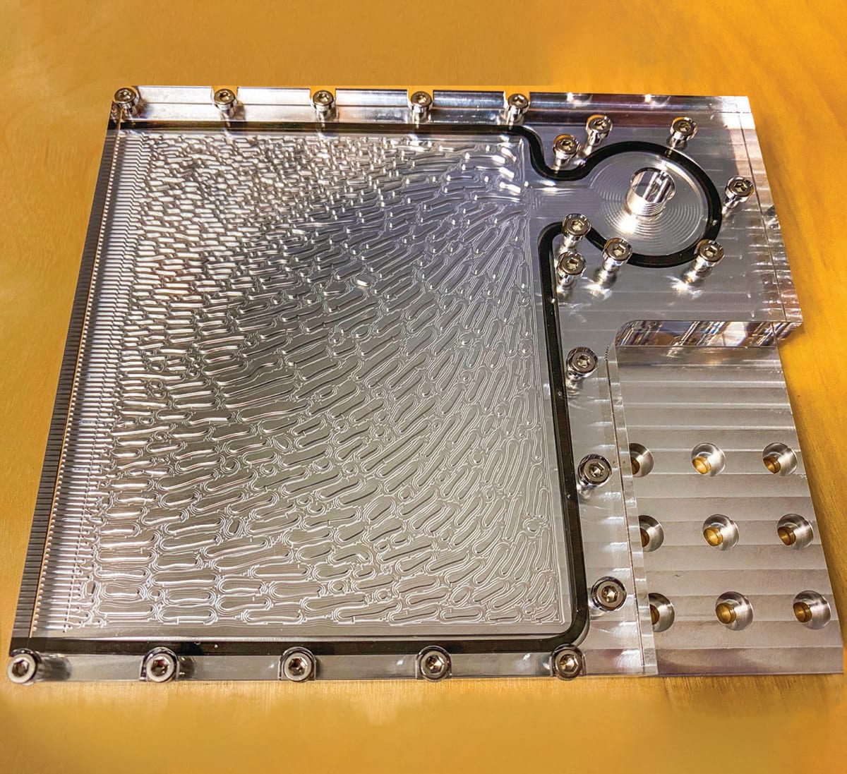
Along with the “flow versus reaction” comparison illustrated above, TRINA produced two further designs (not shown) that combined attributes of those in Figures 3 and 4. Every one of TRINA’s four iterations outperformed baseline conventional designs across key reaction-fluid performance metrics. An additional design that was fabricated and experimentally tested by the TRINA team is shown in Figure 5.
So, what is the ideal design for a flow field plate? There is no such thing, just as there is not a single ideal technology for replacing gasoline-powered automobiles. “From our point of view, we succeed by providing multiple good options for our engineers to consider,” Zhou said.
Zhou also shares some advice that guides him and his colleagues: “Our chief scientist has said: ‘We must stop trying to predict the future, and just work on trying to create it.’”
This article was written by Alan Petrillo, COMSOL Inc. (Burlington, MA). For more information visit here .

