While technology has advanced and there are many new ways to accomplish useful motion within particular applications, electric motors and gearheads are still the preferred and most popular choices for power transmission throughout commercial, industrial, and automation applications. Motors are the components that convert electrical power to useful mechanical power. Gearheads transform the mechanical rotary power to the desired combination of speed and torque if the motor cannot do so directly. Benefits of this combination include low cost, simplicity, reliability, and versatility.

There are several styles and types of electrical motors and power transmission devices on the market today. Depending on the application, a designer might first choose between AC and DC motors, then between styles (e.g., induction, universal, and permanent magnet), and finally between the many types specific to each style. The designer is also challenged with the task of selecting a controlling device and amplifier to provide the proper input power for the electric motor. Within the layout for the power transmission, one can select between options such as direct drive, chain/belt drive, ball screws, direct gearing, and all of the types respective to those styles.
Input Power
As designers put the pieces of the puzzle in place to resolve their applications, they usually hit a hurdle somewhere in the middle; the motor does not provide the proper output. For example, the motor may be capable of supplying the necessary power, but not match the speed or torque requirements. Most motors are rated to operate for peak output around a certain continuous load range of torque and speed. To operate the motor outside that range might either under utilize the motor and result in wasting money on an oversized motor, or over utilize the motor and potentially run the risk of damaging the motor.
Although each type and style of motor operates differently, smaller motors typically operate more efficiently at higher speeds and lower torques. Larger motors operate at higher torques and lower speeds. The dynamics of this is simple to follow once the motor is viewed as a large moment arm. The greater the radius of the rotor the larger the moment that can be created from the motor, resulting in greater torque.
High-energy permanent magnet servo motors have become extremely popular in the motion control industry of late. For these motors, a general rule of thumb is that if the length of the motor is doubled, then the output torque capacity of the motor is also doubled. However, the output torque capacity of the motor will be quadrupled if the length is kept the same and the diameter of the motor is doubled. For maximum efficiency, proper sizing, and a cost effective design, it is best to design the motor for operation at or slightly under its designed load point of speed and torque.
Output Power
Gearing is one of the oldest ways of converting and transmitting rotary power. Most transmission systems operate on the basis of changing moment arm length to alter torque characteristics while inversely changing speed. Torque can easily be doubled by all kinds of transmission systems while simultaneously cutting the speed in half. But, in the end, power in is still equal to power out (less the efficiency). Proper transmission systems must be chosen based on performance, size, cost, and various other constraints. While each type of system has its own pros and cons, gearing systems hold many advantages in areas regarding economic power capacity in small packages.
Involute spur gears have developed to certain standards and offer a highly effective means of transmitting power. Twenty-degree pressure angle involute gears typically are the most popular throughout industry. Simple interaction between two gears results in a change of speed and torque by the same amount as the ratio of the diameters (or tooth count) of the two gears. The power is transmitted through the gear teeth engagements via load sharing across multiple teeth (contact ratio). Because of the 20-degree pressure angle, resultant radial loading on the shaft/journals is introduced into the system. Efficiencies of spur gearing can exceed 98%.
To enhance the output of such a spur gear design, a style of involute spur gearing, known as epicyclic gearing (i.e., planetary gearing), was developed. Planetary gearing dramatically increased the strength of the gearhead while eliminating radial loading by counterbalancing the affect of any one-gear engagement.
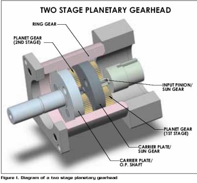
Planetary gearheads distribute the input power coming from the sun gear (input pinion) to two or more planetary gears. Since the planet gears are positioned symmetrical to the pinion gear, radial loading on the pinion gear is eliminated. The planet gears are housed within a ring gear, which has gear teeth cut into the inside diameter in a reversed tooth profile. The separating forces (radial force) produced from the planet gears’ tooth engagements with the sun and ring gears, cancel each other. The ring gear is stationary, and the input sun gear pinion drives the planet gears, which then walk in the same rotational direction as the sun gear.
Counter balanced input force from the sun gear with reaction force from the ring gear, results in a tangential force on the planetary gear axis of rotation to produce this walking motion. The rotary motion and force of the individual planetary axes is cumulatively captured with what is known as a carrier plate and can be directly coupled to either an output shaft, or to another sun gear for the process to repeat through multiple stages (depending on the ratio), see Figure 1.
Depending on the number of teeth of the sun gear and ring gear, each stage typically generates speed reduction ratios between 3 and 10 times the input speed. A two stage planetary gearhead, which has two 10 to 1 stages (i.e., 10 rotations of the input pinion results in one rotation of the output), yields 100 times the output torque (less efficiency) and 1/100 the rpm. If the gearhead were reversed so that the output shaft becomes the input shaft, the speed would increase by 100 times; the available output torque would decrease proportionately.
Options
The speed reducing planetary gearhead as described adheres to: Ratio = (Ns + Nr)/Ns (where Ns = Number of sun gear teeth and Nr = Number of ring gear teeth). There are many variations of epicyclic gearing that can be produced from this style. In some instances, the ring gear can be the driving gear or the output gear. Complex planetary gearing is also possible in which gear clusters are used in the planetary configurations. An automobile transmission is a good example of how several styles of planetary gearing can be utilized together.

Materials, heat treating, gear face width, and altering tooth profiles are additional factors to consider for customizing specific advantages or characteristics into a gearhead. Crowning and tip relief each offer altered performance characteristics. Manufacturing methods also play a major role in performance, lead times, and cost ramifications. Gears can be cast, molded, broached, hobbed, shaped, honed, or ground. Each method has advantages and disadvantages. Greater gearhead design evaluation is necessary if an engineer has specific performance requirements or special considerations for life, precision, noise, temperature, and vibration.
The cost is typically higher for planetary gearing than spur gear clustering because part count and complexity is higher. However, planetary gears present huge improvements in power density (torque), torsional stiffness, and backlash reduction. Typical planetary gearheads also offer reduced size advantages in comparison to belt/chain drives, harmonic drives, and spur gearing. They also usually have greater torque carrying capabilities than the belt/chain drives and harmonic drives of comparable size. Harmonic drives, have fewer ratio combinations, but are exceptionally stiff/accurate and rather expensive.
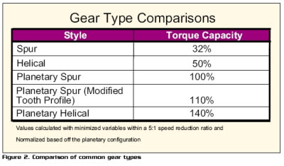
Other types of gearing that have found their way into many applications are bevel gearing (to accommodate non-parallel shafting), worm gearing (for higher ratios in non-parallel shafting and elimination of back-driving potential), and helical gearing. Helical gearing is similar to spur gearing except the teeth of the gears are not straight or parallel to the axis of rotation. Instead they have a helical twist to them. The result of the helix gear mesh is that the contact ratio is increased and the gearhead can be exceptionally strong and smooth. Helical gears can be utilized almost anywhere spur gears are employed. In addition to a cost disadvantage, helical gearing usually produces axial resultant forces on both the drive gear and the driven gear. For this reason all planet gears have to be captivated on both sides of the gear and both the input pinion and output carrier plate/shaft have to be supported with bearings to handle the axial loading. (See Figure 2 for a gear type comparison.)
Software
Recent technology advances in software have also had a dramatic affect on changing the characteristics of gearhead performance through design alterations. One could normally calculate the center distances and tooth count for the planet gear as Np = (Nr-Ns)/2 once the sun gear and the ring gear have been determined. However, this might not optimize the potential gearhead power transmission capacity. Changing the planet gear design allows the engineer flexibility to make changes throughout the other key components of the gearhead. Software designed and enhanced modified gear tooth profiles can optimize the operating center distances as well as operating pitch diameters of the gears, resulting in a stronger gear set. Software packages allow gear producers to maximize performance without adding additional cost.
This article was written by design engineers, at CGI, Inc., 3400 Arrowhead Drive, Carson City, NV, 89706. For more information, contact the design engineering team at

