
The criterion for structural failure must be based on failure modes of the component being designed. If the component is to withstand millions of cycles of load application, criterion for fatigue failure must be used. Fatigue damage caused by repeated dynamic loads depends on the number of cycles and the frequency of significant stresses. Therefore, for accurate prediction of fatigue failure in structural components, accurate prediction of dynamic force histories is required.
An instrumented vehicle was used to capture road load data in actual vehicle operation. Measured signals were analyzed and processed in order to eliminate spikes, drifts, and other effects for use in virtual simulation. The data is reduced in size using a time-correlated fatigue analysis using a damage editing method that retained the most damaging events and removed the non-damaging events from the signal.
The durability test development process for bus body and chassis components required both on-road and laboratory experiments to assess and measure loads. Six-poster rig testing in a laboratory allows repeatability to vehicle testing under service loads, apart from reducing the time taken for the durability test process.
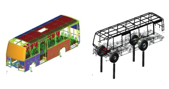
The virtual simulation process has two distinct phases of analyses: Finite element (FE) analysis, and multibody dynamics simulation (MBD). Structures considered in the FE model are frame, bus body, and suspension system. The frame and bus body were modeled with thin shell elements. Aggregate mass was defined with lumped mass elements. The ladder frame comprises two frame side members (FSM) that carry substructures/attachment mountings, suspension, ARB, and bump stop. Bolt connections were simulated using 1D-beam elements, and weld connections were defined with shell elements. Cast suspension mounting brackets were modeled with linear tetrahedral elements.
The Modal Superposition Method (MSM) was used to evaluate the stress response of the structure to transient excitations using natural frequencies and mode shapes from the modal analysis. Fatigue analysis was carried out based on these computed stress histories. Fatigue life prediction was performed by simulating the road load data.
In MBD simulation, the model consists of a flexible frame and bus body structure; the parabolic suspensions were modeled with ADAMS, which captures both the vertical and lateral stiffness. Nonlinear springs, dampers, bump stops, and ARB were modeled with appropriate damper and bush elements. To apply excitations to the vehicle, model actuators were modeled with cylinders connected by a translational joint. Component mass/inertia, geometric location of hard points, payload, and GVW were checked against design values.
Other issues addressed in MBD simulation were model building with flexible bodies for the bus body and chassis frame; the inclusion of nonlinear elements like springs, dampers, and bump stops; and load extraction for use in FE simulation using transient dynamic analysis with compressed and filtered RLD data.
A physical test was conducted in a 6-poster rig using the same road load inputs used for analysis. The test was continued even beyond the intended target life to produce failures in the component. The failure locations estimated from simulation matched with the failures seen in the 6-poster, proving the correctness of the approach followed.
The lifecycles observed were compared with 6-poster laboratory test results. The closeness of the fatigue life ratio between analysis and observed life in test shows that VTM is a practically appropriate approach for analysis of big structures experiencing variable loading.
This work was done by Manimaran Krishnamoorthy and Mathew Sam Paul Albert of Ashok Leyland Ltd.