
Pneumatics have been used in automated machines for well over 100 years, with pneumatic technology developing and evolving for over 1,000 years in some form or another; for example, as boat sails.
There have been many innovations over the years and the basic pneumatic components such as valves, solenoids, cylinders, hoses, and fittings are well developed and mature. These devices can be combined in many ways to provide simple and reliable machine control.
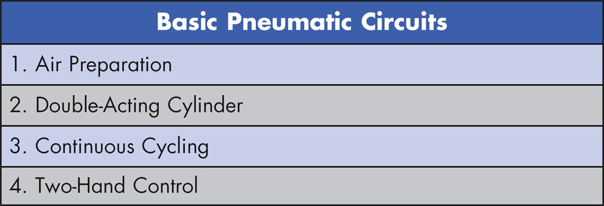
This article examines pneumatic design best practices and then presents four basic pneumatic circuits (Table 1) commonly used in machine automation. While there are many variations, these pneumatic circuits combine basic pneumatic components to create functional and reliable pneumatic circuits.
Pneumatic Design Best Practices
Before discussing these four basic pneumatic circuits, it’s best to review best practices for pneumatic design. While there is a long list of potential pneumatic problems — such as low or varying air pressure, improper use of flow controls, air cylinders banging at power up, and slow or inconsistent cylinder speed — following good pneumatic design practices can address these and other issues.
Prerequisites for implementing pneumatic design best practices are an understanding of pneumatic circuit symbols; types of valves available such as 2-way, 3-way, and 4-way; pneumatic cylinders; and related pneumatic components such as tubes, hoses, flow controls, and air preparation devices.
The starting point for a good pneumatic design is ensuring proper plant supply air pressure. A consistent plant air pressure and flow is needed for pneumatic devices to operate consistently and reliably. Air preparation of the plant supply at the machine is important as well and is the first basic pneumatic circuit discussed below.
To help control the air and the related motion of pneumatic actuators, the cylinder should not be oversized, as this may cause it to stroke slowly due to excess airflow requirements. A properly sized cylinder provides more efficient use of air and moves at a higher speed. A good design will include the use of flow controls to throttle the air exiting the cylinder, which slows down the cylinder motion — generally a desired outcome. The use of cylinders with built-in cushions also helps stop the cylinder at the end of travel. Both the flow control and cushions can help prevent banging and possible damage to the cylinder.
Actuators that move too quickly can cause excessive noise, as can the exhausting of air from valves. Using mufflers on the exhaust ports is a simple design practice that should always be followed to attenuate this noise.
Air Preparation Subsystem
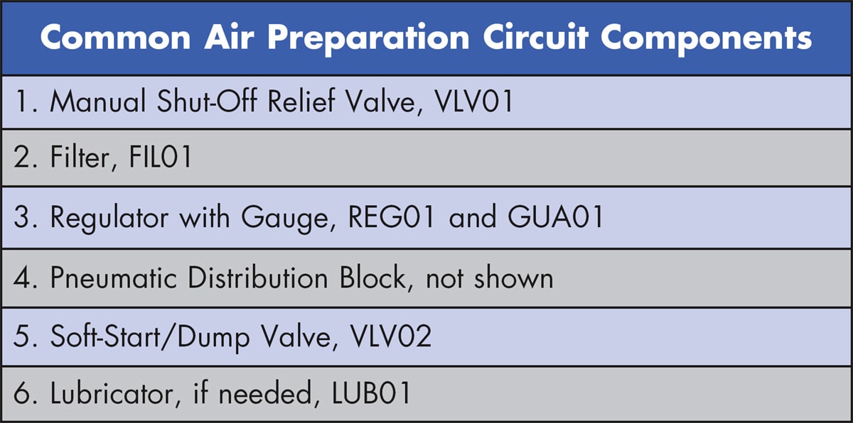
In terms of airflow, the first pneumatic circuit applied in most machines is air preparation. Plant-supplied compressed air needs to be prepped before it feeds air to any other pneumatic circuits on a machine. The air preparation circuit shown in Figure 1 starts with a single-point pneumatic air connection, with its common components listed in Table 2. These devices often include a filter, regulator, and less often, a lubricator (FRL).
The order of the pneumatic devices listed in Table 2 is typically the order the devices are assembled in an air preparation unit but not always. For example, some designs require a manual shutoff relief valve (VLV01) or a pneumatic isolation/lockout valve to be the first component connected to the plant air supply. Others believe it should be mounted after an FRL to ensure clean, dry air flows through the valve.
This valve’s purpose is to remove or dump all the compressed air from the machine. Releasing the air by rotating a manual valve or a push-pull action depressurizes the machine for maintenance and although not shown in Figure 1, this manual valve should be lockable in the OFF position.
Mounting this shutoff valve upstream of the FRL enables maintenance of the FRL at the machine. Without it upstream of the FRL, filter maintenance would be difficult and could affect other equipment in the area when air is dumped for service. Additional plant level, area, or zone air preparation and shutoff units can help protect the shut-off valve at the machine if necessary.
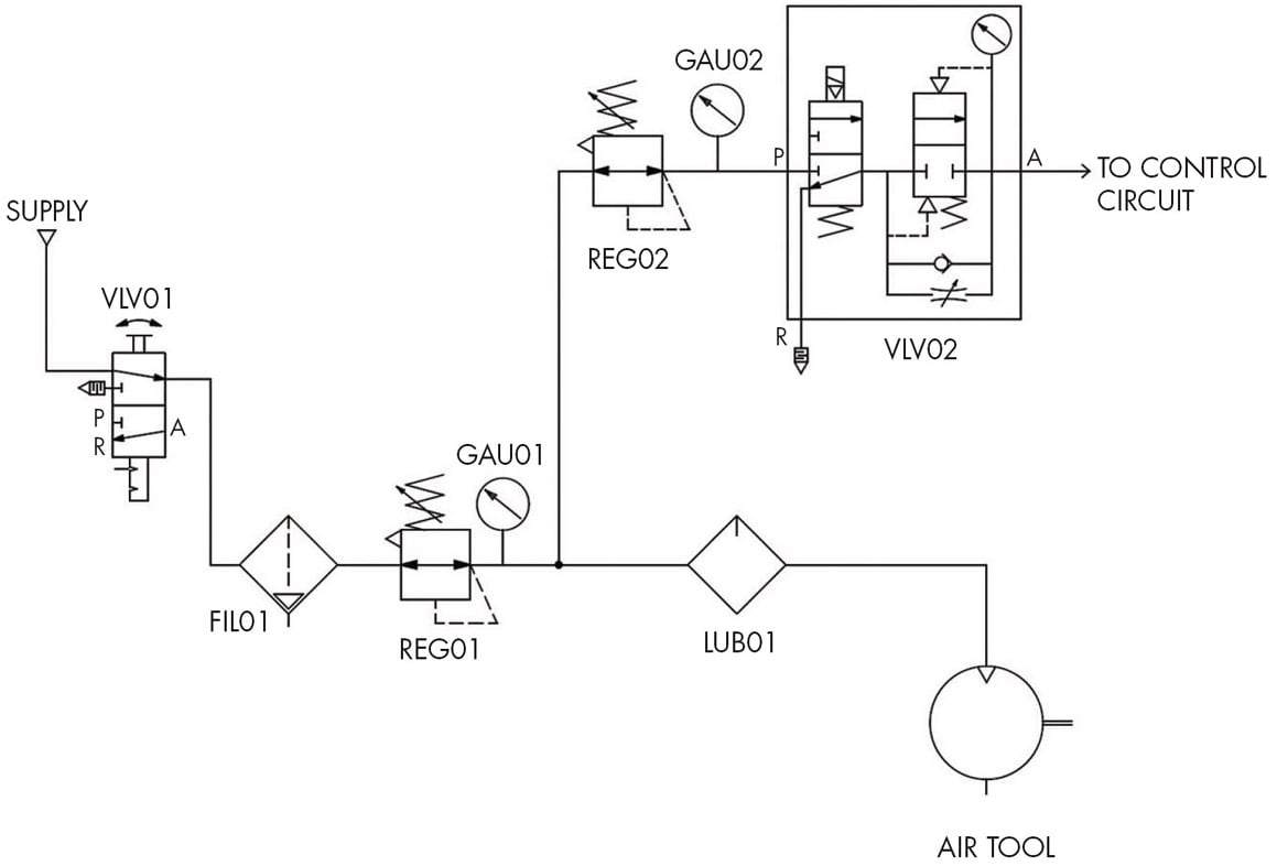
Filter FIL01 is used to remove particulates and separate moisture from the air and it is mounted just downstream of the shutoff valve VLV01. This filter has a liquid drain, indicated by the triangle at the bottom of the symbol, that can be either manual, semiautomatic, or automatic. The symbol does not show detail of the type of drain bowl such as all-metal or guarded. A schematic with a pneumatic panel layout drawing should detail this information, along with additional information such as mounting brackets.
Downstream of the filter is a regulator (REG01) or it may be an integral part of the filter, which would be indicated by a dashed-line box around both filter and regulator. While not shown in the circuit diagram, it is good practice to note the working pressure of the machine and the maximum pressure allowed. A phenolic tag with this information is often attached near the regulator.
A pressure gauge (GAU01) should always be included with a regulator, either built-in or threaded into the pressure port, typically included with the regulator. Often, a pressure switch (not shown in Figure 1) is installed just downstream of the regulator for monitoring pressure okay status. This switch’s output is typically a discrete input to the machine controller such as a programmable logic controller (PLC).
Regulators have input and output ports to ensure proper airflow, in some cases with a relieving feature. The relieving function reduces output air when the regulator is adjusted to a lower pressure. This function also ensures downstream pressure is removed when upstream air is exhausted. The regulator symbols (REG01 and REG02) show they are relieving type, indicated by the triangle at the upper left corner of each device.
The air exiting regulator REG01 produces clean, dry, and filtered air that is then split through a tee fitting or a pneumatic distribution block (not shown). One branch provides a lubricated air supply and the other a non-lubricated supply. The non-lubricated supply feeds a second regulator and then the electrically operated soft-start/dump valve VLV02. This valve typically removes air to motion-causing pneumatic devices, such as cylinders and actuators, for safety. These devices typically don’t need lubricating. When an emergency stop is pressed, power is removed from the valve, which causes it to dump the motion-causing air pressure from the system.
The air prep circuit diagram shown provides lubricated and non-lubricated air. Most pneumatic devices today do not need lubricated air but if lubrication is needed — such as with pneumatic air tools and motors — it should be adjusted for light oiling because too much oil can clog up the pneumatic system components.
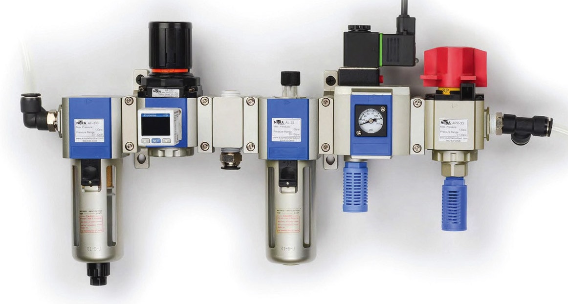
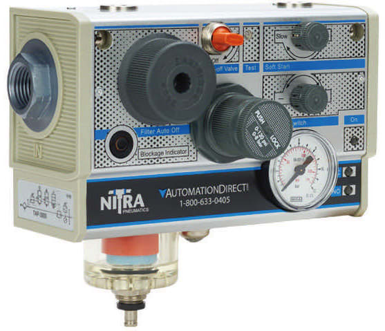
An all-in-one unit (such as the one shown in Figure 2) can be used for air preparation. It combines all the devices discussed in Figure 1, less the lubricator, in one unit. It can be purchased from a vendor with a single part number, saving purchasing, receiving, assembly, and installation time. It also includes a clogged filter indicator, adjustable pressure switch with indicator LEDs, and adjustable port sizes to match the flow rate needed for an application.
Double-Acting Cylinder Circuit
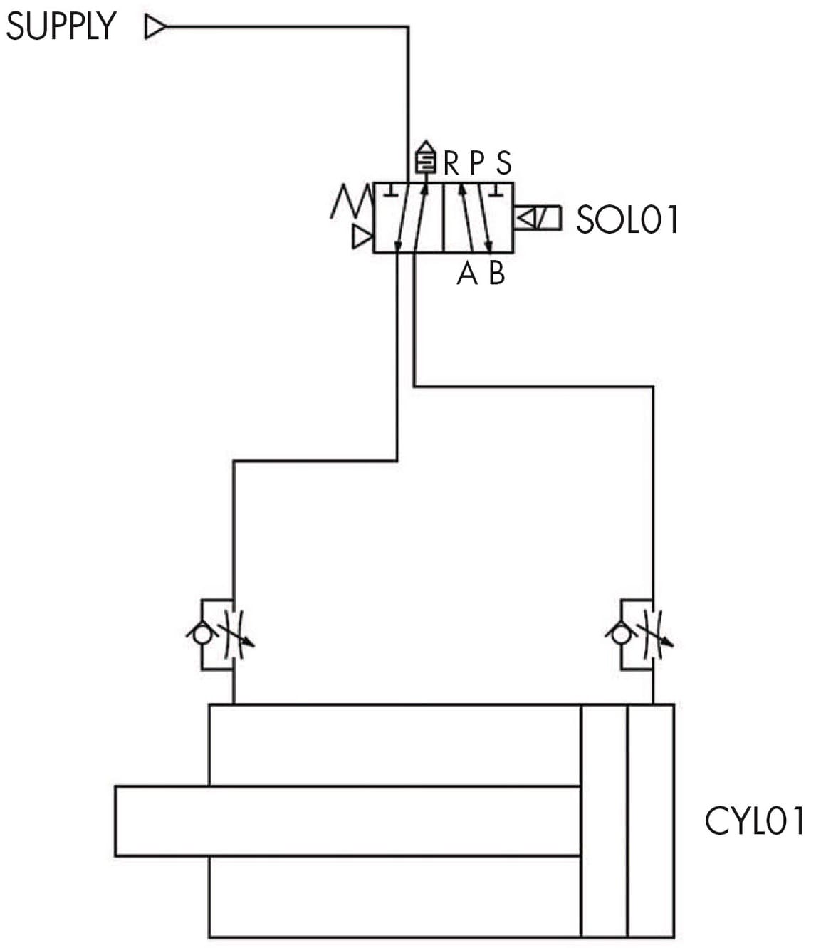
Automation to extend and retract an air cylinder is common in many machines. Figure 3 shows a pneumatic circuit consisting of a 4-way solenoid valve (SOL01) operating a double-acting cylinder (CYL01). Filtered air from the air preparation unit feeds a solenoid valve controlled by a PLC.
The solenoid valve symbol SOL01 indicates it is a single-acting, spring-return valve. This valve is pilot activated, indicated by the triangles at each side of the symbol. These pilot valves are efficient, using a small amount of air to move a large valve spool. However, a minimum amount of air pressure is required to move the spool. This minimum operating air pressure is noted in the valve specification — typically, about 20 psi is needed to ensure the valve operates as designed.
As depicted in the symbol of SOL01, a spring on the left side pushes the valve spool to the right when in its normal resting state (OFF). With the valve off, air is supplied out of port A and flows through an adjustable flow control to the left side of cylinder CYL01, retracting the cylinder. While the cylinder is retracting, air on the right side of the cylinder exits through a flow control device. The check valve around the adjustable flow control device closes, forcing air through the adjustable flow section of the device. These adjustments can be used to throttle the cylinder retract speed. The flow-controlled air then flows through port B of the valve, then through a muffler at port S.
Typically, a valve such as SOL01 is energized by a 24 VDC PLC output. This switches the valve, supplying pressure out port B. Similarly to the normal resting state flow, this air flows freely through the flow control to the extend side of the cylinder, extending the cylinder rod and plunger to the left. The air on the left side of the cylinder is forced out through the flow control. As the air exits to port A of the valve, the flow can be controlled. The air then flows through port A to port R, where a muffler is installed to reduce the exhaust noise.
Continuous Cycling Cylinder Circuit
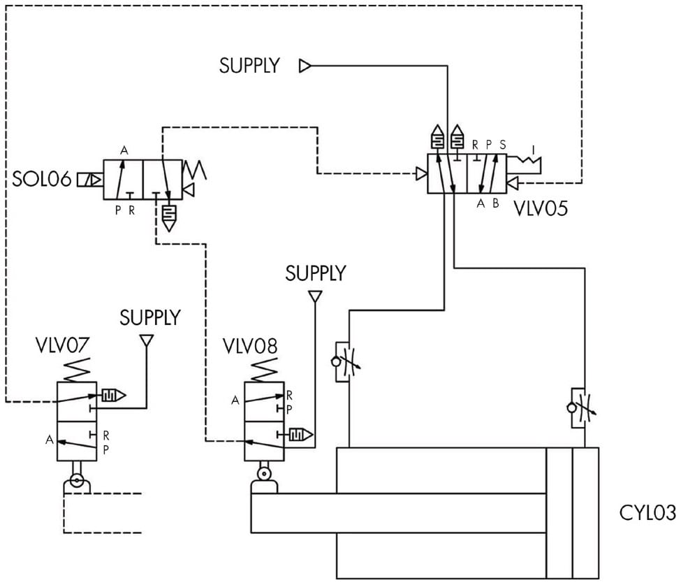
With no external control required, Figure 4 provides a circuit example of how pneumatic components alone can be combined in a well-thought-out design to automatically cycle by simply supplying compressed air to valves VLV05, VLV07, and VLV08.
With compressed air supplied, when solenoid SOL06 is energized with CYL03 physically retracted, the system will start cycling, extending, and retracting cylinder CYL03. In this condition, supply air flows through VLV08 and SOL06, then provides pilot air to directional control valve VLV05. The air supplied through VLV05 causes the cylinder to extend and retract (cycle) in a similar fashion to the double-acting cylinder in Figure 3. To control the cycle speed of the cylinder, flow control valves are used to adjust the flow of air exiting the cylinder.
As cylinder CLY03 extends, it physically operates the 3-way, 2-position spring returned valve VLV07. This valve supplies pilot air to VLV05. The pilot air switches the position of VLV05’s spool, which reverses the direction of CYL03, retracting it. With the cylinder retracted, VLV08 is actuated, supplying pilot air to the other side of VLV05, causing the cylinder to reverse direction and extend. The cycle repeats until SOL06 is de-energized. Once de-energized, the cycle ends once the cylinder retracts.
The key pneumatic logic components of this circuit are the 4-way air-piloted valve (VLV05), which is the directional control valve, and the two 3-way roller-actuated valves (VLV07 and VLV08), which do the same job as electrical solenoids to control the spool position of VLV05. Instead of electricity, pilot air alone controls VLV05. Valves VLV07 and VLV08 are configured like limit switches with a mechanical arm. Cams or flags on the cylinder are used to actuate the valves. When not activated, the valves spring return to their normal position.
Two-Hand Control Circuit
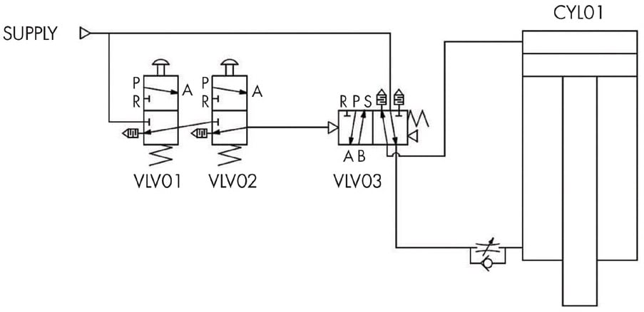
The pneumatic circuit in Figure 5 details a pneumatic two-hand safety control system for a press application. The circuit combines pneumatic buttons VLV01 and VLV02 configured as 3-way valves. These valves feed pilot air to a 4-way valve (VLV03). This circuit also highlights how small valves — the pneumatic pushbuttons — can use pilot air to operate a large valve controlling a large press cylinder with high airflow requirements. Although not shown in this circuit, anti-tiedown checks could be added to further improve the safety of this design.
Both pneumatic buttons must be pressed simultaneously to cascade pilot air to the directional control valve VLV03. The supply of pilot air switches the valve spool, causing the double-acting press cylinder CYL01 to extend. When either pushbutton is released, the spring return function of VLV03 switches the spool back to the normal position, supplying air to the retract side of the press cylinder.
While only one button must be released to retract the press cylinder, if either pneumatic pushbutton is tied down (held pressed), only one button could be used to operate (extend) the press. This would not be safe. In most systems with high press force, additional safety systems would need to be added to check that both buttons have been released after each cycle and that both buttons are pressed at the same time, within about a quarter of a second, before supplying pilot air to the direction valve VLV03. Control reliable features could also be added to ensure a single failure doesn’t allow the system to operate unsafely.
As discussed above, one-way flow control valves throttle the air exiting the cylinder to control the speed. While only the press extend speed is controlled in this circuit, a second speed control could be added to control the retract speed.
An important note when controlling air exiting the cylinder is that air must be present to control the speed. If all the air is exhausted due to an emergency stop or idle air leakage, the cylinder may move very fast the first cycle. To eliminate this problem, sometimes the flow of air into instead of out of the cylinder is used to control its motion.
Additional upgrades to this circuit that are not shown include adding a pressure regulator to control the extend pressure (force) of CYL01. A pressure switch could also be added for error-proofing. The switch would sense that minimum press pressure was met and provide a press force okay signal to a PLC, for example.
The variety of pneumatic circuits is endless but these four basic pneumatic circuit examples show how common pneumatic components can be combined to perform useful automation functions. With a little imagination, FRLs, valves, flow controls, cylinders, buttons, actuators, and other pneumatic components can be combined in a variety of ways to meet the needs of almost any pneumatic system.
(Note that the two-handed circuit described and shown here is a basic functional example, and is not intended to depict a machinery safety design. As with all safety-related equipment designs, designers of such systems must review and comply with applicable requirements as published by OSHA, ISO, and other organizations.)
This article was written by Pat Phillips, Product Manager, Fluid Power & Mechanical Products, AutomationDirect (Cumming, GA). For more information, visit here .