
The term "actuated ball-and-socket" (ABS) characterizes a proposed class of ball-and-socket joints that would incorporate ultrasonic motors and other piezoelectric actuators to generate multidimensional actuation. In some applications, ABS joints could supplant traditional joint-and-actuator assemblies that include passive rotary joints actuated by electromagnetic motors via gears. In comparison with such assemblies, ABS joints offer potential advantages of compactness, relative mechanical simplicity, higher torque-to-weight ratios, no backlash, self-braking with power turned off, and lower cost. ABS joints are expected to be particularly attractive for use as robot joints and as general low-power orienting actuators for diverse applications that could include robot hands, tools, and mechanisms for aiming scientific instruments.
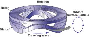
Figure 1 illustrates an ultrasonic motor similar to those that would be included in an ABS joint. This motor includes a washerlike rotor spring-loaded into contact with a washerlike stator. The stator includes a ring of piezoceramic actuator elements that are bonded to a base stator substructure, on the stator face opposite that in contact with the rotor. The piezoceramic elements are positioned at circumferential intervals and are electrically connected in alternating polarity. When electrically excited by waveforms with a proper phase difference, the piezoceramic elements deform in such a manner as to induce a wave that travels circumferentially around the stator. This wave can be amplified by the resonance of the stator and can have an amplitude of the order of several micrometers. As this wave travels around the stator, it causes points on the free surface of the edge of the stator to travel in small elliptical orbits. At crests of the wave, the stator pushes against the rotor, so that through friction, some of the elliptical motion is converted to rotary motion of the rotor.
Figure 2 depicts an ABS joint. A spherical rotor would fit in a housing that would contain bearings. The housing would also contain three drive units (A, B, and C) — each for rotation about one of three axes. These axes, which span three-dimensional space, intersect at the center of the rotor. (The axes are not necessarily perpendicular.) Power and control cables would be connected to each drive unit.
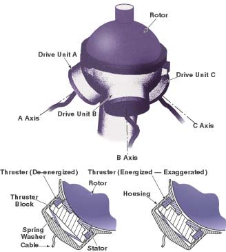
Within each drive unit, a thruster block would support an ultrasonic-motor stator. This stator would likely be somewhat more complex than that of Figure 1: among other things, its rotor-contact surface would likely be spherical, with a radius matching that of the rotor. Notwithstanding the added complexity, the basic principle of operation would be the same as that of the ultrasonic motor described above. By suitable electrical excitation of the stator, the rotor could be made to rotate about the axis of symmetry of the drive unit. A spring washer would push the thruster block, and thus the stator, radially against the rotor. The rotor/stator friction associated with this radial preload would establish the holding (braking) torque in the absence of applied power.
A piezoceramic ring, denoted the thruster, would be located between the thruster block and a shelf in the housing. When not energized, the thruster would not exert any effect. When electrically energized, the thruster would push the thruster block radially outward (against the spring washer), thereby pulling the stator out of contact with the rotor. Thus, energizing the thruster would prevent the drive unit from either driving or braking the rotor.
To avoid working against the holding torque of the other drive units, only one drive unit at a time could be used to produce rotation. For example, in order to obtain rotation about axis A, it would be necessary to (1) excite the stator of drive unit A with appropriately phased waveforms while (2) energizing the thrusters of drive units B and C to prevent these units from braking the rotation about axis A. To move the rotor from an initial orientation to a desired final orientation, it would be necessary to generate a trajectory consisting of a sequence of small rotations about the A, B, and C axes. It would be necessary to develop an electronic data-processing and control system to compute and implement the coordinated, sequential actuation of the three thrusters and the three ultrasonic-motor stators to generate the trajectory. It has been estimated that, in a typical application, the increments of rotation would be characterized by frequencies of the order of a kilohertz.
This work was done by Issa Nesnas of Caltech for NASA's Jet Propulsion Laboratory. For further information, access the Technical Support Package (TSP) free on-line at www.nasatech.com/tsp under the Machinery/Automation category.
NPO-20984
This Brief includes a Technical Support Package (TSP).
Actuated Ball-and-Socket Joints
(reference NPO-20984) is currently available for download from the TSP library.
Don't have an account?
Overview
The document discusses the development and potential applications of actuated ball-and-socket joints (ABS) designed by NASA's Jet Propulsion Laboratory. These joints are characterized by their compact, lightweight, and cost-effective design, making them suitable for various applications, particularly in robotics and aerospace.
At the core of the ABS joint is an ultrasonic motor that operates based on the principle of converting elliptical motion into rotary motion through friction. The design includes a spherical rotor housed within a structure that contains three drive units, each capable of rotation about one of three axes. This configuration allows for multidimensional movement, as the axes intersect at the rotor's center, enabling complex motion in three-dimensional space.
The document details the operational mechanics of the ABS joint, emphasizing the role of electrical excitation in controlling the rotor's movement. A spring washer applies a radial preload to the stator, which enhances the friction between the rotor and stator, establishing a holding torque that maintains the joint's position when power is not applied. This feature is crucial for applications requiring precise control and stability.
The ABS joints are designed to be relatively simple and inexpensive compared to traditional joint-and-actuator systems, which often involve more complex mechanical components. The use of ultrasonic motors allows for smoother and more efficient operation, potentially leading to advancements in robotic systems and other technologies that require precise movement and control.
The document also includes a disclaimer regarding the use of trade names and the lack of endorsement by the U.S. government or NASA for any specific products mentioned. It highlights the collaborative effort between the Jet Propulsion Laboratory and NASA in developing this technology, underscoring the importance of innovation in the field of robotics and space exploration.
In summary, the document presents a promising approach to joint design through the use of actuated ball-and-socket joints, showcasing their potential to enhance the functionality and efficiency of robotic systems and other applications in various fields. The innovative use of ultrasonic motors and the design's inherent simplicity position ABS joints as a significant advancement in mechanical engineering.