
This elemental space radiator heat pipe is designed to operate in the 700 to 875 K temperature range. It consists of a C–C (carbon-carbon) shell made from poly-acrylonitride fibers that are woven in an angle interlock pattern and densified with pitch at high process temperature with integrally woven fins. The fins are 2.5 cm long and 1 mm thick, and provide an extended radiating surface at the colder condenser section of the heat pipe. The weave pattern features a continuous fiber bath from the inner tube surface to the outside edges of the fins to maximize the thermal conductance, and to thus minimize the temperature drop at the condenser end. The heat pipe and radiator element together are less than one-third the mass of conventional heat pipes of the same heat rejection surface area.
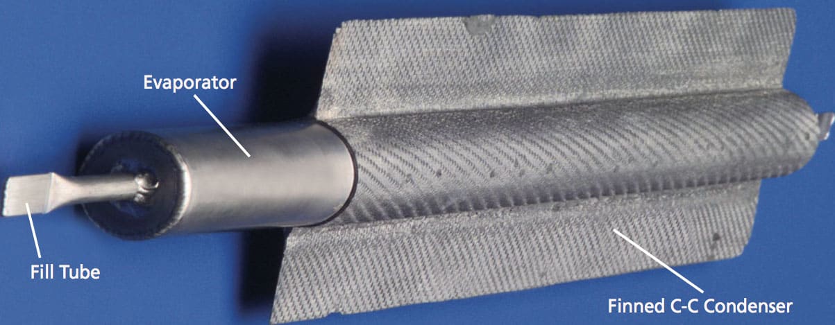
The external section of this liner, which was formed by a “Uniscan” rolling process, transitions to a larger wall thickness. This section, which protrudes beyond the C–C shell, constitutes the “evaporator” part of the heat pipe, while the section inside the shell constitutes the condenser of the heat pipe (see figure). The metal liner contains a concentric tubular perforated wick sized and located to form an annular gap between itself and the inner surface of the liner. The wick is fabricated from molybdenum foil and contains evenly spaced circular perforations. One end of the wick is welded to the evaporator end cap, while the other end is left free.
During the fabrication process, the finned C–C shell condenser section is exposed to an atomic oxygen (AO) ion source for a total AO fluence of 4 × 10²⁰ atoms/cm2, thereby raising its surface emissivity to values between 0.85 and 0.90 at design operating temperature, thus reducing the radiator area required for a specified value of heat rejection to space. The prototype heat pipe performed well in initial low power tests. Based on test results and computer modeling, the heat pipe should be capable of transporting heat at a rate of 900 W at evaporator temperatures in the 850 to 875 K range. Computer modeling also indicates that, if scaled up from a prototype length of 36 cm to a full design length of 91 cm, the heat pipe should be capable of transporting heat at a rate of 2.2 kW at the same evaporator temperature range. At its 1.45 kg/m2 specific mass for two-sided heat rejection, its power-to-mass ratio will be 6.5 kW/kg.
This work was done by Albert J. Juhasz of Glenn Research Center. For more information, download the Technical Support Package (free white paper) at www.techbriefs.com/tsp under the Mechanics/Machinery category.
Inquiries concerning rights for the commercial use of this invention should be addressed to
NASA Glenn Research Center
Innovative Partnerships Office
Attn: Steve Fedor
Mail Stop 4–8
21000 Brookpark Road
Cleveland
Ohio 44135.
Refer to LEW-18307-1.