
The figure depicts a traveling-wave ruby maser that has been designed (though not yet implemented in hardware) to serve as a low-noise amplifier for reception of weak radio signals in the frequency band of 31.8 to 32.3 GHz. The design offers significant improvements over previous designs of 32-GHz traveling-wave masers. In addition, relative to prior designs of 32-GHz amplifiers based on high-electron-mobility transistors, this design affords higher immunity to radio-frequency interference and lower equivalent input noise temperature.
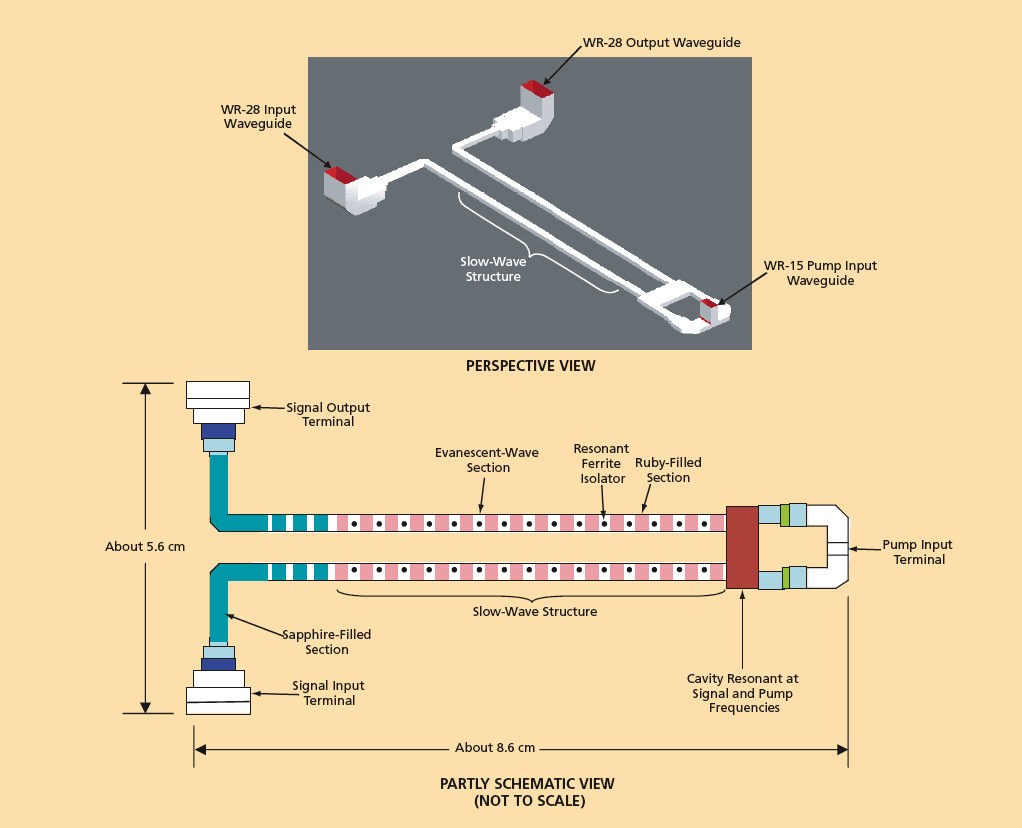
A key feature of the design is a slow-wave structure, the metallic portions of which would be mechanically relatively simple in that, unlike in prior slow-wave structures, there would be no internal metal steps, irises, or posts. The metallic portions of the slow-wave structure would consist only of two rectangular metal waveguide arms. The arms would contain sections filled with the active material (ruby) alternating with evanescent-wave sections. This structure would be transparent in both the signal-frequency band (the aforementioned range of 31.8 to 32.3 GHz) and the pump-frequency band (65.75 to 66.75 GHz), and would impose large slowing factors in both frequency bands. Resonant ferrite isolators would be placed in the evanescent-wave sections to provide reverse loss needed to suppress reverse propagation of power at the signal frequency.
This design is expected to afford a large gain-bandwidth product at the signal frequency and efficient coupling of the pump power into the paramagnetic spin resonances of the ruby sections. The more efficiently the pump power could be thus coupled, the more efficiently it could be utilized and the heat load on the refrigerator correspondingly reduced. To satisfy the requirement for operation over the 0.5-GHz-wide signal- frequency band, the paramagnetic spin resonances would be broadened by applying a magnetic field having a linear gradient along the slow-wave structure. The gradients in the two arms are offset in order to compensate for the gaps of the evanescent sections.
The two arms of the slow-wave structure would be connected into a U-shaped assembly. At the base of the U (at the right end in the figure) there would be a cavity that would be simultaneously resonant in the TE301 mode at the signal frequency and in the TE403 mode at the pump frequency. The pump power would be injected into this cavity from two dielectric-filled waveguides that would be beyond cut-off at the signal frequency. The dielectric-filled waveguides would be excited from the two output arms of an electric-field-plane T junction. The signal power would enter and leave via WR-28 waveguides connected to opposite ends of the U-shaped assembly. Impedance matching would be effected by means of dielectric-filled (sapphire) sections of the waveguide arms near their input and output ends.
This work was done by James Shell and Robert Clauss of Caltech for NASA’s Jet Propulsion Laboratory. NPO-41273
This Brief includes a Technical Support Package (TSP).
Traveling-Wave Maser for 32 GHz
(reference NPO-41273) is currently available for download from the TSP library.
Don't have an account?
Overview
The document outlines the development of a Traveling-Wave Maser (TWM) designed for operation at 32 GHz, specifically targeting the Ka-band downlink frequency allocation of 31.8-32.3 GHz. The primary objective was to create a low noise maser amplifier that could function effectively within a commercial 4 Kelvin cryocooler, while also being simple to manufacture to reduce fabrication costs.
Previous attempts to construct TWMs at this frequency faced significant challenges, including the need for tight physical tolerances and difficulties in impedance matching the input and output signals. These earlier designs utilized coupled TEM mode resonators with metallic slow wave structures, which required high pump power levels and lacked a clear understanding of the microwave pump magnetic field geometry.
The innovative solution presented in this document involves a novel slow wave structure that effectively slows down both the signal and pump frequencies. This design allows for the injection of pump power without disrupting signal propagation. The maser employs a U-configuration slow wave structure made from alternating ruby-filled and evanescent sections of waveguide, which is transparent at both the signal and pump frequencies. The structure avoids the use of metal steps, irises, or posts, simplifying the design.
At the base of the U-structure is a cavity that resonates simultaneously at both the signal (TE301 mode) and pump (TE403 mode) frequencies. The pump power is introduced through dielectric-filled waveguides that are beyond cut-off at the signal frequencies, ensuring efficient energy transfer. Impedance transformers made from dielectric-filled waveguide sections are utilized to match the signal into the slow wave structure.
A key feature of this TWM is its ability to achieve a large gain-bandwidth product at signal frequencies, which enhances performance. The use of ferrite materials in the evanescent sections of the waveguide helps to provide stable amplification by minimizing reverse loss. Additionally, the ruby linewidth is broadened to meet a 500 MHz bandwidth requirement through the application of a linear magnetic field gradient along the slow wave structure.
This TWM is designed for optimal performance when cooled below 4 Kelvin, and the document references a detailed study titled “A 32-Gigahertz Traveling-Wave Maser Design” by J. Shell and R. Clauss, published in the IPN Progress Report. The advancements presented in this document highlight significant progress in maser technology with potential applications in aerospace and telecommunications.