
In a proposed improvement of tooling for friction stir welding, gimballed shoulders would supplant shoulders that, heretofore, have been fixedly aligned with pins. The proposal is especially relevant to self-reacting friction stir welding.
Some definitions of terms, recapitulated from related prior NASA Tech Briefs articles, are prerequisite to a meaningful description of the proposed improvement. In friction stir welding, one uses a tool that includes (1) a rotating shoulder on top (or front) of the workpiece and (2) a pin that rotates with the shoulder and protrudes from the shoulder into the depth of the workpiece. In conventional friction stir welding, the main axial force exerted by the tool on the workpiece is reacted through a ridged backing anvil under (behind) the workpiece. When conventional friction stir welding is augmented with an autoadjustable pin-tool (APT) capability, the depth of penetration of the pin into the workpiece is varied in real time by a position- or force-control system that extends or retracts the pin as needed to obtain the desired effect.
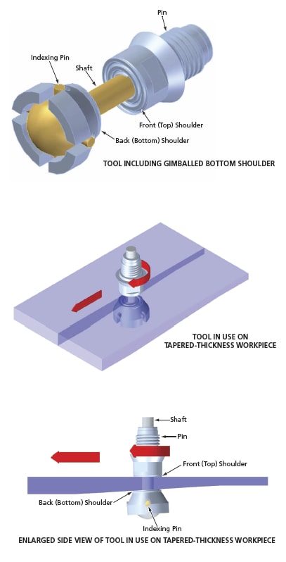
One consequence of the fixed alignment of the shoulders with the pin is that if the thickness of the workpiece or the slope of either surface of the workpiece varies as the tool moves along the workpiece, then the leading or trailing edge(s) of one or both shoulder(s) tend to dig into the workpiece, generating excessive flashing along the weld. The proposed improvement would be a simple, relatively inexpensive means of preventing or reducing such digging. The gimballing of either or both shoulder(s) would enable the tool to better adapt to curvatures and other local variations in the slopes of workpiece surfaces, without need for a complex, expensive shoulder-angle control system.
The figure depicts a representative tool for self-reacting friction stir welding incorporating the proposed improvement. [In this case, the bottom shoulder (only) would be gimballed. Optionally, both shoulders or the top shoulder (only) could be gimballed.] The shaft would be terminated in a ball, from which indexing pins would protrude radially at angular intervals of 90° in a plane perpendicular to the pin/shaft axis. The indexing pins would define gimbal axes. The bottom shoulder would contain slots that would loosely engage the indexing pins. The configuration of the indexing pins and slots would be such that the bottom shoulder would be forced to rotate with the pin and shaft and the pins would hold the back (bottom) shoulder axially in place against tension, yet the looseness of the pin/slot engagement would allow limited rotation of the bottom shoulder about the gimbal axes to accommodate local variations in the slope of the lower surface of the workpiece.
This work was done by Robert Carter and Kirby Lawless of Marshall Space Flight Center.
This invention is owned by NASA, and a patent application has been filed. For further information, contact Sammy Nabors, MSFC Commercialization Assistance Lead, at sammy.