
An optical heterodyne interferometer that can be used to measure linear displacements with an error -20 pm has been developed. The remarkable accuracy of this interferometer is achieved through a design that includes (1) a wavefront split that reduces (relative to amplitude splits used in other interferometers) self interference and (2) a common-optical-path configuration that affords common-mode cancellation of the interference effects of thermal-expansion changes in optical-path lengths.
The most popular method of displacement-measuring interferometry involves two beams, the polarizations of which are meant to be kept orthogonal upstream of the final interference location, where the difference between the phases of the two beams is measured. Polarization leakages (deviations from the desired perfect orthogonality) contaminate the phase measurement with periodic nonlinear errors. In commercial interferometers, these phase-measurement errors result in displacement errors in the approximate range of 1 to 10 nm. Moreover, because prior interferometers lack compensation for thermal-expansion changes in optical-path lengths, they are subject to additional displacement errors characterized by a temperature sensitivity of about 100 nm/K. Because the present interferometer does not utilize polarization in the separation and combination of the two interfering beams and because of the common-mode cancellation of thermal-expansion effects, the periodic nonlinear errors and the sensitivity to temperature changes are much smaller than in other interferometers.
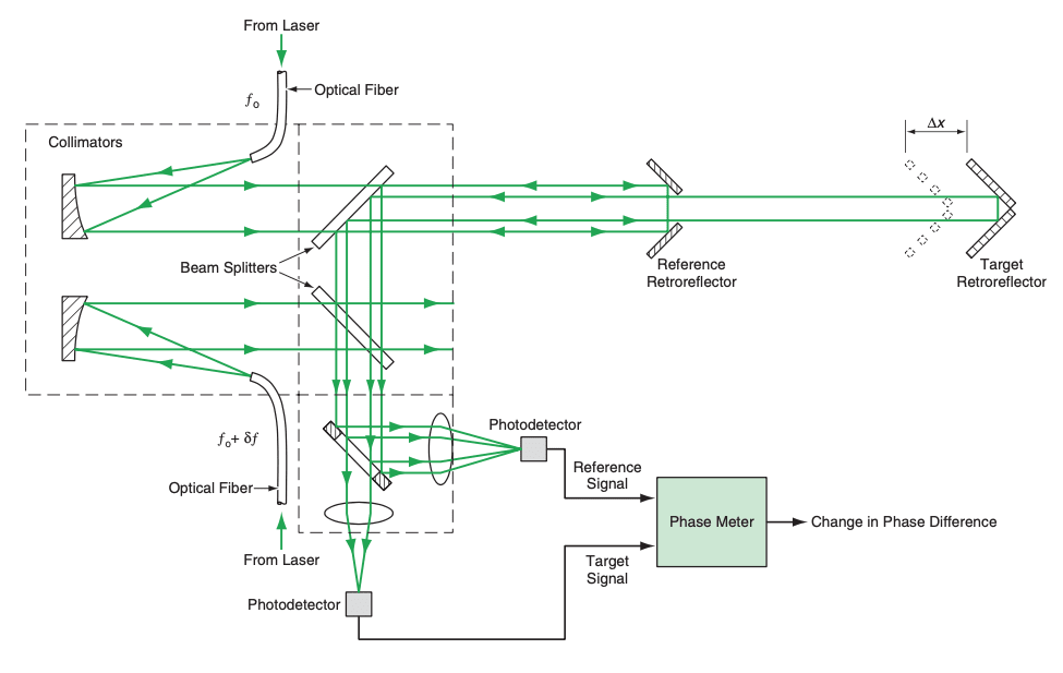
The present interferometer (see figure) makes use of two stable, collimated laser beams - one at a frequency of f0, the other at the slightly different frequency of f0+df. The f0 wavefront is split into two or more sections by a retroreflective reference device that could be, for example, a truncated corner-cube reflector or a mirror with holes. The portion of the f0 wavefront reflected by the reference device serves as reference wavefront. The portion of the f0 wavefront not reflected by the reference device is directed to a target in the form of a retroreflector. The target is mounted on the object, the displacement of which one seeks to measure relative to the reference device.
The light reflected by the target travels back through the optical system alongside the retroreflected reference light. Along the way, both the target and reference light beams pass through a beam splitter where the f0+df beam is superimposed upon them. Then by use of truncated mirrors and lenses, (1) the target signal and part of the f0+df signal are sent to one photodetector while (2) the reference signal and part of the f0+df signal are sent to another photodetector. The lowest-frequency components of the heterodyne outputs of the two photodetectors are signals of frequency df, the difference between the phases of which is proportional to the amount by which the length of the target path exceeds that of the reference path. Any displacement ∆x, of the target along the optical path results in a proportional change in this phase difference. Hence, measurement of the phase difference and of any change in the phase difference yields information on the displacement. One can calculate the displacement by use of the equation
∆x = λ∆φ/4Π,
where λ is the wavelength of the laser light and ∆f is the change in the phase difference.
This Heterodyne Interferometer is used to measure the displacement ∆φ. In addition to the advantages mentioned in the main text, this interferometer contains fewer parts and can be fabricated with looser tolerances, relative to a typical prior interferometer designed for performing the same measurement.
This work was done by Feng Zhao of Caltech for NASA's Jet Propulsion Laboratory.
This invention is owned by NASA, and a patent application has been filed. Inquiries concerning nonexclusive or exclusive license for its commercial development should be addressed to
the Patent Counsel
NASA Management Office-JPL; (818) 354-7770.
Refer to NPO-21221.
This Brief includes a Technical Support Package (TSP).
Interferometer for Measuring Displacement to Within 20 pm
(reference NPO21221) is currently available for download from the TSP library.
Don't have an account?
Overview
The document presents an innovative interferometric apparatus developed by Feng Zhao at NASA's Jet Propulsion Laboratory (JPL) for ultra-high precision displacement measurement. This technology is particularly significant for applications requiring extreme accuracy, such as the Space Interferometry Mission, which demands measurements with an accuracy of approximately 100 picometers over distances of 20 meters.
The core of the invention is a heterodyne interferometer that utilizes two stable, collimated laser beams with slightly different frequencies: one at frequency ( f_0 ) and the other at ( f_0 + \delta f ). The ( f_0 ) wavefront is split by a retroreflective reference device, which can be a corner-cube reflector or a specialized mirror. This setup allows for the generation of a reference wavefront and a target wavefront, with the latter directed towards a retroreflector mounted on the object whose displacement is being measured.
The document highlights the novel approach of using a wavefront split instead of the traditional amplitude split, which significantly reduces self-interference and enhances measurement accuracy. While existing devices typically achieve accuracy in the range of 1-10 nanometers, this new design can achieve precision down to 20 picometers. Additionally, the common mode design of the interferometer minimizes temperature sensitivity, which is a critical factor in maintaining measurement accuracy. Existing devices often suffer from temperature-induced errors, with sensitivities around 100 nm/K, whereas this invention is designed to be orders of magnitude less sensitive to temperature fluctuations.
The document outlines the motivation behind this development, addressing the limitations of conventional displacement measurement techniques, such as periodic nonlinearity and thermal sensitivity. By employing a wavefront split approach, the invention effectively mitigates issues related to polarization leakage and compensates for temperature changes, thus enhancing the reliability of the measurements.
In summary, this document details a significant advancement in interferometric technology, showcasing a novel design that promises to improve the precision and reliability of displacement measurements in various scientific and engineering applications. The invention is patented by NASA, and inquiries for commercial development are directed to the Patent Counsel at JPL.