
The figure illustrates an improved electronic circuit that excites constant-magnitude vibrations in an electrostatically actuated, capacitively sensed mechanical resonator. The circuit can be adapted, for example, to a planar vibratory microgyroscope like the one described in the preceding article.
Mounted on the moving part of the resonator are two electrodes - the driven and the sensing plates - that face corresponding fixed driven and sensing plates. Each pair of electrodes serves as a capacitor; the driven one for electrostatically exciting vibrations, the sensing one for measuring the vibrational velocity. Through the negative-feedback path of the transconductance amplifier, the fixed sensing plate becomes charged up to the dc bias applied to the "+" terminal of the transconductance amplifier. As the resonator vibrates, the voltage across the sensing capacitor thus remains constant, although its capacitance varies at a rate proportional to the vibrational velocity. By the fundamental relationship among capacitance, voltage, and charge, a current proportional to the vibrational velocity must therefore flow between the sensing plate and the "-" input of the transconductance amplifier. As a result, the transconductance amplifier puts out a voltage proportional to the vibrational velocity.
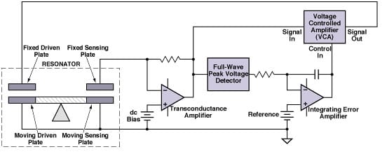
The output of the transconductance amplifier is fed to the signal-input terminal of the voltage-controlled amplifier (VCA) and to the input terminal of the full-wave peak detector. The integrating amplifier produces an error signal that is the integral of the difference between (1) the peak-detector output (which is proportional to the magnitude of the vibrational velocity) and (2) the reference voltage, which represents a desired magnitude of vibration. The error signal is fed to the control-input terminal of the VCA. The output of the VCA is proportional to the velocity and is fed back to the fixed drive plate. With sufficient gain in the amplifiers, the resonator and feedback loop oscillate together. When the amplitude of oscillation is too high or too low, the error signal adjusts the gain of the VCA to drive the magnitude of vibration toward the desired value represented by the reference voltage.
This work was done by Christopher Stell, Vatché Vorperian, Roman Gutierrez, and Tony Tang of Caltech for NASA's Jet Propulsion Laboratory.
NPO-20088
This Brief includes a Technical Support Package (TSP).
Vibration-Regulating Circuit for a Mechanical Resonator
(reference NPO20088) is currently available for download from the TSP library.
Don't have an account?
Overview
The document presents a technical support package detailing a vibration-regulating circuit for mechanical resonators, developed by a team at NASA's Jet Propulsion Laboratory (JPL). The primary goal of this innovation is to maintain constant magnitude vibrations in electrostatically actuated, capacitively sensed mechanical resonators, which are crucial for applications such as microgyroscopes.
The circuit operates using a transconductance amplifier, which is connected to a single sense capacitor. A DC bias is applied to the amplifier's positive terminal, allowing the fixed sensing plate to charge and maintain a constant voltage across the sensing capacitor, even as the resonator vibrates. This setup ensures that the capacitance varies in proportion to the vibrational velocity, enabling accurate measurement of the resonator's motion.
The output from the transconductance amplifier is fed into a voltage-controlled amplifier (VCA) and a full-wave peak detector. The peak detector provides a signal proportional to the vibrational velocity, while an integrating error amplifier computes the difference between this signal and a fixed reference voltage, which represents the desired vibration magnitude. The resulting error signal adjusts the gain of the VCA, which in turn regulates the feedback to the resonator's drive plates, ensuring that the vibrations remain at the desired level.
This two-loop feedback system is designed to achieve equilibrium, where the gain of the VCA converges on the precise value needed for the desired displacement. The document highlights several novel aspects of this approach, including the use of a single sense capacitor for displacement regulation, the application of a DC bias instead of an AC signal, and the focus on velocity feedback rather than position feedback.
The invention addresses a significant challenge in the operation of bulk silicon micro-machined vibratory gyroscopes, where maintaining consistent mechanical displacement is critical for accuracy. The circuit's design allows for effective regulation of vibrations despite variations in the resonator's quality factor (Q), which can be affected by factors such as pressure changes and manufacturing defects.
Overall, this vibration-regulating circuit represents a significant advancement in the field of mechanical resonators, offering improved performance and reliability for precision applications in aerospace and other industries.