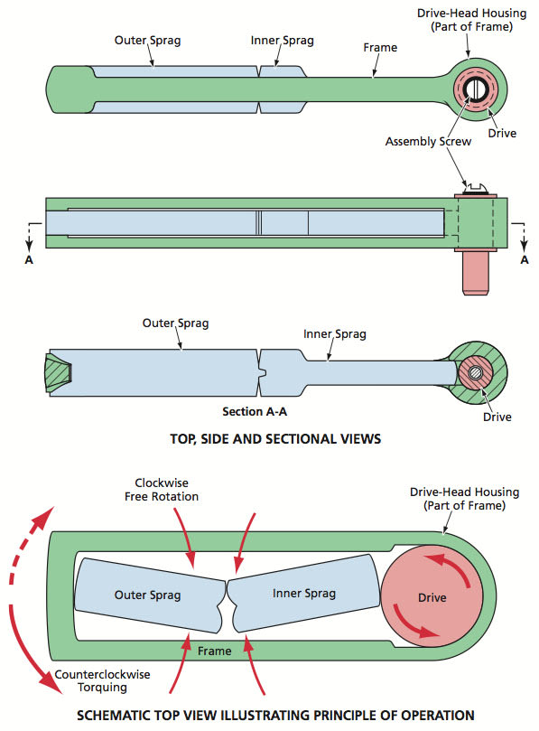
Sprag handle wrenches have been proposed for general applications in which conventional pawl-and-ratchet wrenches and sprag and cam “clickless” wrenches are now used. Sprag handle wrenches are so named because they would include components that would function both as parts of handles and as sprags (roller locking/unlocking components). In comparison with all of the aforementioned conventional wrenches, properly designed sprag handle wrenches could operate with much less backlash; in comparison with the conventional clickless wrenches, sprag handle wrenches could be stronger and less expensive (because the sprags would be larger and more easily controllable than are conventional sprags and cams).
A basic sprag handle wrench, shown in the upper part of the figure, would include the following parts:
- A frame that would constitute both the drive-head housing and part of the handle,
- A drive that would rotate freely within the drive-head housing except when engaged by sprags,
- An outer sprag that would constitute the rest of the handle, and
- An inner sprag that would engage the outer sprag at its outer end and the drive head at its inner end.
The frame would include a gap, into which the two sprags could be placed. Taken together, the inner sprag, the drive-head housing, and the drive would constitute the drive head. The inner and outer sprags would act as a roller-locking/unlocking pair that would afford low-backlash ratcheting, as described below.

In clockwise torquing, depicted schematically in the lower part of the figure, the operator would push or pull on the outer-sprag portion of the handle in a clockwise direction; this action would jam the inner and outer sprags together between the frame at the outer end and the drive at the inner end. The jamming of the inner sprag against the drive would prevent rotation of the drive relative to the drive housing, so that clockwise torque would be exerted on the drive. At the end of the clockwise torque-application stroke, the operator would twist the outer sprag to relieve the contact forces as described above. Then by exerting a small counterclockwise force on the outer-sprag portion of the handle, the operator could further unjam the sprags to complete the disengagement with the drive, and turn the handle counterclockwise to the starting position for the next clockwise torque-application stroke. Except for reversal of the directions of all forces, torques, and rotations, counterclockwise torquing and ratcheting would be the same as in the clockwise case described above.
This work was done by John M. Vranish of Goddard Space Flight Center. For further information, contact the Goddard Innovative Technology Partnership (ITTP) Office at (301) 286-5810. GSC-14682-1

