
Blade health monitoring continues to gain interest as a means of assessing the health of turbine airfoils in aerospace and ground-based gas turbine engines in fleet operation. Many types of blade sensors are used throughout the design validation process of new engines that would theoretically provide information for blade health monitoring. However, most of these sensors are either too difficult to use or do not have sufficient survivability to monitor blades throughout the operational life of the engine.
As engine OEMs work to gain further efficiency from the engine and closed-loop clearance control becomes viable on production engines, the same data can be used for engine health monitoring as well. One of the biggest challenges for any tip clearance sensor is long-term survivability. Due to the high temperatures within the turbine, the components in this area are made of expensive alloys, and have ceramic coatings and complicated cooling passages since the gas path temperatures normally exceed the melting points of the metals. Any sensors operating in this area must be made of a similar construction.
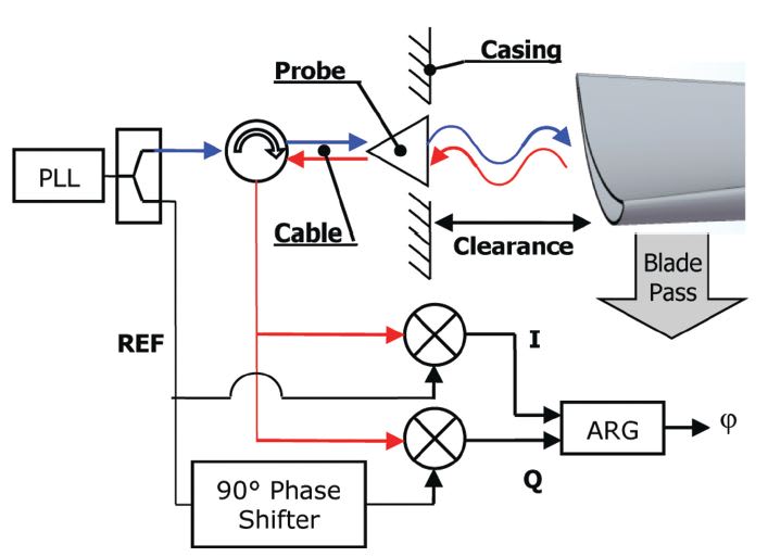
A microwave clearance sensor was originally developed for active clearance control applications and designed for long-term operation. The sensor might be applied to health monitoring applications within the turbine. The micro wave blade tip clearance sensor is based on a phase measurement principle. A continuous- wave microwave signal is generated within the microwave electronics and transmitted through a coaxial cable to the probe (Figure 1). The probe serves as an antenna, guiding the continuous wave into the space between the casing and the bladed rotor. The probe serves as both a transmitter and receiver, capturing the micro waves reflected back to the blade tip, which is then measured by the electronics.
The microwave probe serves as an antenna optimized to transmit at a defined frequency with a given bandwidth. This antenna is packaged into a hermetic sealed body with an integral mineral cable. This probe construction is made with materials chosen for hightemperature survivability and longterm operation in the harsh environment of gas turbines.
Two versions of the microwave system have been developed. The first one uses a frequency in the 6-GHz band, has a measurement range of 25 mm, and a probe diameter of 14 mm. It is suited for large-frame gas turbines. The second one uses a frequency in the 24-GHz band for a measurement range of 6 mm, and a probe diameter of 8.5 mm. It is preferably used with small blades in aviation or aeroderivative gas turbines.
The probe installation requires an opening through the casing such that the probe tip has a direct view of the rotor and its blade tips. A ceramic window on the probe tip allows the microwave signal to transmit to the blade. A retaining ring ensures that this ceramic window does not fall into the gas path.
Depending on the engine construction, the integration into the engine can be complex. Normally, the installation in the turbine section has more constraints due to the high temperatures and to ensure proper sealing between several casing layers, which can move relative to each other.
Figure 2 shows an example of probe mounting in the turbine section of an aero engine with two casing layers. The probe tip is usually installed flush or recessed from the casing inner surface to ensure no contact with the blades even during a rub event.

Key considerations in blade tip clearance sensing for engine condition monitoring are the sensitivity, repeatability, linearity, and overall accuracy of the sensor. Accuracy is an often-discussed metric for tip clearance when applied to active clearance control; however, sensitivity and repeatability are the primary metrics to be used for engine condition monitoring.
Clearance measurements within the turbine can provide a large amount of data useful for condition monitoring. Some of the important aspects for clearance sensor performance include individual blade measurements, sensitivity, linearity, and repeatability. A 24-Ghz clearance sensor was demonstrated in both the laboratory and within the engine environment showing the ability to measure the key parameters for condition health monitoring.
This work was done by Jonathan L. Geisheimer, David Kwapisz, Thomas Holst, and Michael Hafner of Meggitt Sensing Systems. The full technical paper on this technology is available for purchase through SAE International at http://papers.sae.org/2013-01-2145 .