
Streamlined fairings have been invented for housing single or multiple microphones to measure noise in flowing gases and liquids. Each fairing of this type is designed to minimize the spurious (background) component of noise generated by local flow disturbances caused by the fairing itself. These fairings could be used in measuring noise associated with a variety of flow sources, including aircraft, wind tunnels, air-handling equipment, and land vehicles.
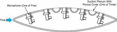
The figure presents a cross section of a representative fairing of the present type. The microphones are mounted flush with the outer fairing surfaces to minimize acoustic distortion; in fairings invented previously for the same purpose, the microphones are typically mounted within recesses or cavities, the acoustic resonances of which distort the desired acoustic signals. Also, unlike some previously invented fairings, the microphones are not mounted behind porous screens that attenuate the desired acoustic signals. The outputs of the microphones are communicated to measuring or recording equipment via electrical or fiber-optic cables, or by telemetry.
To minimize the local flow disturbances that generate background noise, a fairing of this type is designed to obtain laminar flow under the widest practical range of anticipated flow conditions. In the example illustrated in the figure, the shape of the fairing and its orientation with respect to the flow are chosen to obtain an extended upstream surface with a favorable pressure gradient (pressure on the fairing surface decreasing with distance from the leading edge).The flow in a favorable pressure gradient tends to be naturally smooth or laminar over a wide range of speed; consequently, microphones placed in this region are exposed to minimum noise from local flow disturbances.
Above a critical speed that depends on the roughness of the fairing surface and the disturbance content of the free-stream flow, the flow along the upstream surface undergoes a transition from laminar to turbulent. The transition speed can be increased by cooling and/or by suction through small holes, slots, or porous surfaces; this phenomenon is well known in the aircraft industry and has been exploited to reduce drag on aerodynamic surfaces. Here, suction is applied to maintain laminar flow at speeds that would otherwise exceed the transition speed.
The pressure along the fairing surface downstream of the point of maximum thickness is increasing with downstream distance. The flow in this adverse pressure-gradient region tends to be turbulent at most speeds of interest, and the flow may separate from the fairing. Unsteady separation may cause an increase in drag and levels of self-noise. Suction control may also be used to delay the onset of flow separation at the trailing edge.
This work was done by William Clifton Horne and Kevin D. James of Ames Research Center.
Inquiries concerning rights for the commercial use of this invention should be addressed to
the Patent Counsel
Ames Research Center; (650) 604-5104
Refer to ARC-14241.