
A method of estimating phase drifts of microwave signals distributed to, and transmitted by, antennas in an array involves the use of the signals themselves as phase references. The method was conceived as part of the solution of the problem of maintaining precise phase calibration required for proper operation of an array of Deep Space Network (DSN) antennas on Earth used for communicating with distant spacecraft at frequencies between 7 and 8 GHz. The method could also be applied to purely terrestrial phased-array radar and other radio antenna array systems.
A prior method of measuring phase drifts involves the use of reference-frequency signals separate from the transmitted signals. A major impediment to accurate measurement of phase drifts over time by the prior method is the fact that although DSN reference-frequency sources separate from the transmitting signal sources are stable and accurate enough for most DSN purposes, they are not stable enough for use in maintaining phase calibrations, as required, to within a few degrees over times as long as days or possibly even weeks. By eliminating reliance on the reference-frequency subsystem, the present method overcomes this impediment.
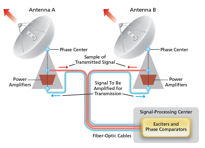
In a DSN array to which the present method applies (see figure), the microwave signals to be transmitted are generated by exciters in a signal-processing center, then distributed to the antennas via optical fibers. At each antenna, the signals are used to drive a microwave power-amplifier train, the output of which is coupled to the antenna for transmission. A small fraction of the power-amplifier-train output is sent back to the signal-processing center along another optical fiber that is part of the same fiber-optic cable used to distribute the transmitted signal to the antenna. In the signal-processing center, the signal thus returned from each antenna is detected and its phase is compared with the phase of the signal sampled directly from the corresponding exciter. It is known, from other measurements, that the signal-propagation path length from the power-amplifier-train output port to the phase center of each antenna is sufficiently stable and, hence, that sampling the signal at the power-amplifier-train output port suffices for the purpose of characterizing the phase drift of the transmitted signal at the phase center of the antenna.
In this method, the phase comparison is performed continuously while the transmitting frequency is ramped as a known function of time. On the basis of the fundamental relationships among frequency, phase, and signal-propagation path length, it can be shown that if the sweep for a given antenna is started at frequency f and the phase-comparison measurement is found to change by an amount Δθ when the frequency has changed by an amount ΔΔf, then
Δθ = (2π/c)(fΔd + dΔf+ ΔdΔf),
where c is the speed of light in the fiber-optic cable or other signal-propagation medium and Δd is the change in the path length during the frequency-sweep interval. If the frequency is ramped over an interval just large enough to cause Δθ = 2π and the ramp is rapid enough that Δd is negligible during the measurement time interval, then after straightforward algebraic manipulation of the above equation for Δθ, the electrical length can be estimated by the simple equation d = c/Δf.
It must be recognized that the phase-comparison measurement used in this method is a round-trip phase-difference measurement: as such, it does not inherently distinguish between roundtrip and one-way phase effects. Inasmuch as the primary goal of the measurement is to estimate the phase drift at the phase center of the antenna, it is important to distinguish between (1) round-trip phase accumulation, for which approximately half of the measured phase applies at the phase center, and (2) phase drifts in the power-amplifier train, which are one-way effects that contribute in their entirety to the phase drift at the phase center of the antenna.
This work was done by Leslie Paal, Ryan Mukai, Victor Vilnrotter, Timothy Cornish, and Dennis Lee of Caltech for NASA’s Jet Propulsion Laboratory. NPO-44611
This Brief includes a Technical Support Package (TSP).
Estimating Transmitted-Signal Phase Variations for Uplink Array Antennas
(reference NPO-44611) is currently available for download from the TSP library.
Don't have an account?
Overview
The document titled "Estimating Transmitted-Signal Phase Variations for Uplink Array Antennas" (NPO-44611) from NASA's Jet Propulsion Laboratory addresses significant challenges in maintaining the calibration phase vector for uplink arraying systems. These calibrations can occur infrequently, sometimes only every few days, leading to issues with phase drifts that can adversely affect signal integrity, particularly at X-band frequencies (7-8 GHz) and higher.
One of the primary challenges highlighted is the instability of frequency references used in the Deep Space Network (DSN). While these references are generally stable for most applications, they are not sufficiently stable over extended periods (days or weeks) to maintain the required phase accuracy for uplink arraying. This instability can introduce phase drifts that must be corrected before applying the calibration vector.
To address this issue, the document proposes a novel solution that utilizes the transmitted X-band carrier signal itself as a reference phase. This approach eliminates the reliance on separate frequency references, which tend to degrade over time. By using the transmitted signal, the system can accurately monitor and correct for phase drifts over extended periods, potentially lasting days or weeks.
The technical implementation involves a phase comparator assembly (PCA) located in SPC-10. The PCA uses the output from exciters generating the uplink RF signal as the reference local oscillator (LO) frequency. The signal is then distributed to the 34-meter transmitter antennas located approximately 16 kilometers away via fiber optic cables. These cables can expand and contract due to thermal effects, introducing phase shifts after calibration. However, the proposed technique allows for a sample of the amplified signal to be returned to the PCA for comparison with the transmitted carrier phase. This enables the measurement and removal of damaging phase drifts from the Uplink Array calibration vector before operational uplinking of critical data to spacecraft.
In summary, the document presents a significant advancement in the field of uplink arraying by providing a method to monitor phase drifts without relying on unstable frequency references. This innovation enhances the accuracy and reliability of data transmission in space communications, which is crucial for successful missions. For further inquiries, contact information for NASA's Innovative Partnerships Program is provided.