
A design concept for the receiver portion of a proposed free-space optical communication terminal calls for integration of its communication and pointing detectors. As explained below, this would entail a departure from prior designs, in which pointing and communication detectors have been separate.
As used here, "communication detector" denotes a single high-speed photodetector used for reception of a laser beam that has been modulated to convey information, while "pointing detector" denotes an array of photodetectors (typically, a quad-cell detector or a charge coupled device) used in sensing the pointing error (the error in the aim of a receiver telescope, relative to the laser beam axis). The pointing detector of this or any free-space optical-communication receiver is necessary for proper acquisition and tracking of the received laser beam. The suitably processed output of the pointing detector is fed back to a fine-steering mirror to reduce any pointing error and thereby maintain optimum reception.
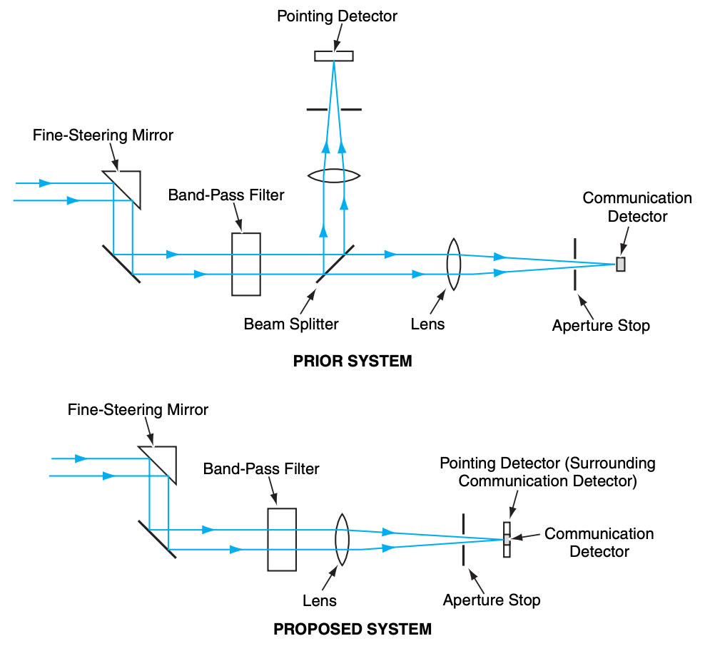
Heretofore, it has been common practice to pass the incoming laser beam through a beam splitter that sends about 10 percent of the beam power to a pointing detector and the rest to a separate communication detector, as illustrated in the upper part of the figure. One disadvantage of this is that because only 10 percent of the received signal power is available for use by the pointing detector, the signal-to-noise ratio (SNR) at the pointing detector is lower than it otherwise would be. The performance of the pointing detector is correspondingly limited. Another disadvantage is that the alignment between the communication and pointing detectors is critical and must be ensured by means of a calibration procedure.
According to the proposal, there would be no beam splitter. The communication and pointing detectors would be positioned coaxially in the same focal plane, as shown in the lower part of the figure: the communication detector would occupy the central part of the focal plane, while the pointing detector would occupy the surrounding area. This arrangement would inherently ensure the proper alignment of the detectors with each other.
The dimensions of the signal and pointing detectors would be chosen to take advantage of the Gaussian distribution of signal power in the focal plane. The communication detector would be sized to receive 85 percent of the received signal power at zero pointing error (in other words, when the received laser beam was centered on the focal plane). The reason for choosing this size is that it would maximize the SNR in the communication detector in the presence of background light.
During zero pointing error, the remaining 15 percent of the received signal power would impinge on the pointing detector. This would be half again as much signal power as is available to the pointing detector in the beam-splitter approach. Even more advantageously, during nonzero pointing error, the proportion of signal power available to the pointing detector would increase by a large amount because the Gaussian peak would no longer be centered on the communication detector. For example, if the pointing error were such as to place the half-power radius of the beam at the center of the focal plane, then the power incident on the pointing detector would increase to five times that of the beam splitter approach. This increase in power would help to make it possible to correct rapidly for large pointing disturbances — for example, those caused by wind.
This work was done by Michael Britcliffe and Daniel Hoppe of Caltech for NASA's Jet Propulsion Laboratory. For further information, access the Technical Support Package (TSP) free on-line at www.techbriefs.com/tsp under the Electronics/Computers category.
In accordance with Public Law 96-517, the contractor has elected to retain title to this invention. Inquiries concerning rights for its commercial use should be addressed to:
Innovative Technology Assets Management
JPL
Mail Stop 202-233
4800 Oak Grove Drive
Pasadena, CA 91109-8099
(818) 354-2240
E-mail: This email address is being protected from spambots. You need JavaScript enabled to view it.
Refer to NPO-30647, volume and number of this NASA Tech Briefs issue, and the page number.
This Brief includes a Technical Support Package (TSP).
Integrated Pointing and Signal Detector for Optical Receiver
(reference NPO-30647) is currently available for download from the TSP library.
Don't have an account?
Overview
The document discusses an innovative Integrated Communications and Pointing Detector designed for optical communication receivers, developed under NASA's Jet Propulsion Laboratory. Traditional optical communication systems typically utilize separate detectors for signal detection and telescope pointing error sensing, which can lead to inefficiencies and performance limitations. The new integrated detector addresses these issues by combining both functionalities into a single coaxial detector located at the focal plane.
This integrated system significantly enhances communication performance by 10% and improves pointing detection performance by 50%. It also increases the sensitivity for signal acquisition by a factor of five or more. The design features a communication detector that captures 85% of the energy in the focal plane when the telescope is accurately pointed, while the remaining 15% is distributed across an array of pixels for pointing detection. This configuration allows for real-time alignment of segmented telescopes and eliminates the need for calibration, as the alignment between the detectors is inherently maintained.
One of the key advantages of the integrated detector is its ability to respond rapidly to disturbances, such as wind, by providing an exponential increase in energy available for pointing detection as the telescope moves off bore-sight. For instance, if the telescope is misaligned to the half-power point of the beam, the integrated detector can deliver a fivefold increase in power to the pointing detector compared to traditional beam-splitting methods.
The document includes schematic illustrations that depict the design and energy distribution of the coaxial detector system. The communication detector is specified to be 0.1 mm in diameter, with a pixel size of 10 µm for the pointing and alignment array, although these dimensions may vary based on specific applications.
Overall, this integrated approach not only enhances the performance of optical communication systems but also simplifies the design by reducing the number of components required. The advancements presented in this document highlight the potential for improved efficiency and reliability in deep-space optical communications, making it a significant contribution to aerospace technology.