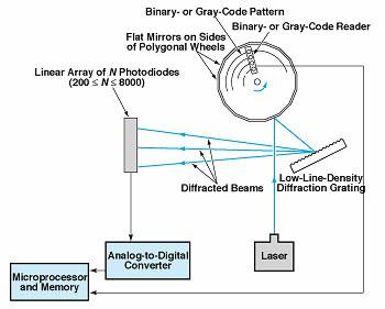
The apparatus shown schematically in the figure is an optoelectronic shaft-angle encoder that measures absolute angles with high resolution. This encoder is an improved version of the apparatus described in "High-Resolution Optoelectronic Shaft-Angle Encoder" (GSC-13543), Laser Tech Briefs, Vol. 2, No. 2, (Spring, 1994), page 32.

Like the prior encoder, this one includes a polygonal mirror wheel affixed to the shaft, the angular position of which is to be measured. A binary- or Gray-code pattern on the wheel is read by a binary- or Gray-code reader, thereby indicating the shaft angle, with coarse resolution, to within the increment of angle subtended by one side of the polygon. Equivalently, the output of the binary- or Gray-code reader identifies which side of the polygon lies along a given line of sight.
A helium/neon or other compact laser sends a narrow, low-divergence beam of monochromatic light toward the polygonal mirror wheel. One of the mirror facets reflects the laser beam onto a nearby low-line-density diffraction grating. The light diffracted from the grating strikes a linear array of photodiodes at several spots. The outputs of the photodetectors are digitized, providing fine-resolution data on the distribution of light diffracted onto the array. These data are fed to a microprocessor for calculation of the shaft angle as explained below.
The spatial distribution of light diffracted onto the array depends on the wavelength of the light, the precise nature and spacing of the grating lines, and the geometry of all of the optical components. Among other things, the positions of the diffraction spots on the array depend on the position and angle of incidence of the reflected laser beam on the grating and these, in turn, depend on the angle of the facet, which depends on the angle of rotation of the shaft.
The distribution of light on the array is thus a known function of the angle of the facet. This function is inverted to compute the angle of rotation of the shaft, to fine resolution, modulo the coarse-resolution increment of angle. The coarse-resolution reading is then added to the fine-resolution angle to obtain the absolute shaft angle to fine resolution.
As explained thus far, the apparatus functions similarly to the prior encoder. The fundamental difference lies in the use of a single diffraction grating separate from the polygonal mirror instead of (1) a diffraction grating mounted on each face of the polygonal mirror in one prior encoder or (2) simple polygonal mirror facets with no diffraction grating in the other prior encoder. The geometric relationships among the optical components of the present apparatus result in approximate doubling of the number of diffraction orders available for measurement on the array; this provides additional design flexibility for doubling the angular resolution, or for making the apparatus more compact with a somewhat smaller increase in resolution.
The present design also reduces the cost significantly. Fabrication of a polygonal mirror with diffraction-grating facets for the prior encoder is difficult and time consuming and costs as much as $20,000. In contrast, a separate polygonal mirror and grating can be made in less time and with less difficulty, at a cost between $3,000 and $5,000.
This work was done by Douglas B. Leviton of Goddard Space Flight Center. For further information, access the Technical Support Package (TSP) free on-line at www.nasatech.com/tsp under the Electronics & Computers category.
This invention is owned by NASA, and a patent application has been filed. Inquiries concerning nonexclusive or exclusive license for its commercial development should be addressed to
the Patent Counsel
Goddard Space Flight Center; (301) 286-7351.
Refer to GSC-13611.

