
The “polished panel” optical receiver concept described here makes use of aluminum panels on the main reflector of the Deep Space Network’s (DSN’s) 34-meter antennas at optical wavelengths by polishing and coating their surface to efficiently reflect nearinfrared wavelengths in the 1,064–1,550- nanometer range. Achievable surface smoothness is not a limiting factor for aluminum panels, and initial field experiments indicate that the surface quality of microwave aluminum panels is sufficient to concentrate the light into small, but not diffraction-limited, spots at their primary focus. Preliminary analysis of data from high-quality microwave panels has shown that the light can be concentrated into 200–400 microradian cones, resulting in spot diameters of 2–4 mm at the 10-meter primary focus F0 shown in the figure, or 2–4 cm spots at F1 after magnification by the subreflector, which results in an effective focal length of about 100 meters. Three distinct implementation options are possible, with theoretically identical tracking and communications performance:
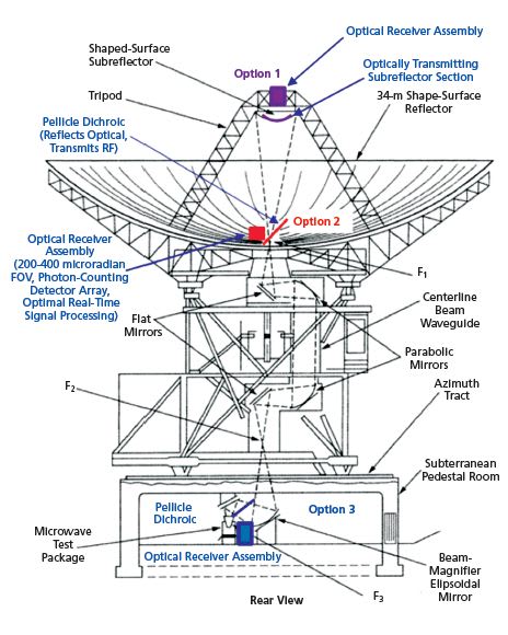
Option 2: Alternately, the optical com munications assembly could be located near the first available focal-spot F1 following reflection by the subreflector (which would have to be polished), next to the input to the beam waveguide on the main reflector as shown in the figure. This placement requires an RF/optical dichroic that reflects optical but transmits RF wavelengths, which can be implemented as a dielectric-coated pellicle, similar to commercial pellicle dichroics currently available in sufficiently large sizes. However, since this placement requires the pellicle to transmit large amounts of RF power in transmit mode, careful design will be required to ensure that the pellicle is not damaged due to absorption of RF energy during uplink transmission. Since the effective focallength after subreflector magnification is about 100 m, the estimated spot-size at F1 is 2–4 cm in diameter, requiring the development of large-area photon-counting array detectors for best performance. However, the spot-size can be decreased by a factor of 3 to about 1 cm using commercially available optics, relaxing the requirements on the detector array to manageable proportions. Option 3: Finally, the optical communications assembly could be placed inside the pedestal room, and separated from the RF signal after the ellipsoid and before the signal reached the microwave receiver via an RF/optical dichroic near F3, as shown in the figure. This placement would require polishing and coating the inner portions of all five mirrors of the beam waveguide (BWG) to very high optical reflectivity, but would have the advantage of protecting the optical communications assembly from the elements. If the mirrors could be polished to 95% reflectivity, then a loss of 0.955=0.77 would occur to both the optical signal and the background, which is only about 1 dB and hence would not impact communications performance significantly. However, this option is the most complicated to implement, requiring large-scale resurfacing of the BWG mirrors in addition to polishing the subreflector, hence it would likely incur the greatest cost.
For either approach, the reflected light is filtered using a narrowband optical filter to minimize background interference. At 1,550-nm wavelength, filter bandwidths of 2 Å are feasible, with high peak transmission (80%) suitable for communications applications. Detailed analyses of tracking and communication performance of a generic polished-panel optical receiver is presented in other papers where pulse-position modulation and photon-counting detection are assumed, and it is shown that typical mission requirements to Mars can be met using polished-panel optical receivers even when pointing close to the Sun. Note that since receiver performance depends on field-of-view rather than spot-size, the analysis presented in these papers applies equally to both design options.
In addition to theoretical analyses, preliminary polished-panel experiments are underway at the Venus site (DSS-13), located at the Deep-Space Communi cations Complex in Goldstone, Cali fornia. These experiments are designed to measure the actual spot-size of a polished DSN panel as well as a more precise polished ALMA panel originally designed for near THz (900 GHz) operation. The key concepts of closed-loop tracking using detector arrays, as well as precise measurement of communications parameters while tracking stars and bright planets simulating future deep-space laser sources, will be determined in a realistic field environment and evaluated to predict future deep-space communications performance.
This work was done by Victor A. Vilnrotter and Daniel J. Hoppe of Caltech for NASA’s Jet Propulsion Laboratory. For more information, contact