
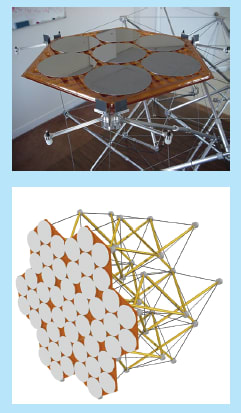
The upper part of Figure 1 shows a small-scale prototype of a developmental class of lightweight, deployable structures that would support panels in precise alignments. In this case, the panel is hexagonal and supports disks that represent segments of a primary mirror of a large telescope. The lower part of Figure 1 shows a complete conceptual structure containing multiple hexagonal panels that hold mirror segments.
An important product of the present development effort is the engineering practice of building a lightweight, deployable structure as an assembly of tensegrity modules like the one shown in Figure 2. This module comprises two octahedral tensegrity subunits that are mirror images of each other joined at their plane of mirror symmetry. In this case, the plane of mirror symmetry is both the upper plane of the lower subunit and the lower plane of the upper subunit, and is delineated by the mid-height triangle in Figure 2. In the configuration assumed by the module to balance static forces under mild loading, the upper and lower planes of each subunit are rotated about 30°, relative to each other, about the long (vertical) axis of the structure. Larger structures can be assembled by joining multiple modules like this one at their sides or ends.

Simple algebraic expressions have been derived to describe the deformations, under load, of multimodule platelike and mast structures, thereby making it possible to design such structures without need for computers. Perhaps the most important rules for designing a tensegrity structure are that (1) the lengths of the struts and cables are critical and they determine the unloaded shape of the structure, but that (2) the preloads (discussed in the next paragraph) in the cables and struts determine the degree of rigidity under external load.
To make a module stowable, it is necessary to provide for disconnection of the ends of many of the struts and/or make the struts collapsible (e.g.,tele- scoping). To make a module deployable, one must provide means to reconnect the struts if disconnected and re-extend them if collapsed. The means of deployment must include means to apply the required preloads to the cables and struts. In cases of manual stowage and deployment, such means can include toggles and turnbuckles. For automated deployment, more sophisticated means are needed. In the structure of Figure 2, the struts are telescoping piston/cylinder units that are extended pneumatically and locked at full extension by spring-loaded mechanisms.
This work was done by Glenn W. Zeiders of the Sirius Group, Larry J. Bradford of CAT Flight Services, and Richard C. Cleve of Elk River Engineering for Marshall Space Flight Center. For further information,contact: Glenn W. Zeiders Sirius Group 2803 Downing Court Huntsville, AL 35801 E-mail: