
A technique for adjusting the resonance frequency of a single-mode round cylindrical microwave cavity has been proposed to maximize the transfer of power from a magnetron to one or more sample(s) of material that have been placed in the cavity for microwave heating. Unlike an older technique that involves insertion of a dielectric stub into the cavity from an off-axis position, the proposed technique would preserve the desired angular symmetry of the electromagnetic mode. Unlike another older technique that involves moving a plunger along the cylindrical (z) axis, the proposed technique would be applicable to z-independent as well as to z-dependent modes.
For maximum transfer of power, the resonance frequency of the cavity must be maintained within the fixed frequency band (typically 5 to 15 MHz wide) of the magnetron. The need for tuning arises because the samples exert a detuning effect: they alter the resonance frequency by an amount that increases with the real part of the permittivity of the sample material. In general, insertion of samples causes the resonance frequency to decrease from the empty-cavity value. Moreover, the permittivities of most materials vary with temperature; in a typical case, the real part of the permittivity increases with temperature, leading to a further lowering of the resonance frequency during microwave heating.
The proposed technique would exploit the detuning effect of dielectric objects. Provision would be made for adjustable insertion of one or more concentric dielectric tuning object(s) (described below). The cavity would be constructed with a radius slightly less than the value needed to match the resonance of the magnetron in the empty-cavity condition; thus, prior to insertion of any objects into the cavity, the resonance frequency of the cavity would be higher than the nominal magnetron resonance frequency. Specifically, the radius of the cavity would be chosen, according to calculations of the resonance frequencies under various conditions, so that the insertion of the samples and the dielectric tuning object(s) would cause the resonance frequency to decrease to within the tuning range of the magnetron. The position of one of the dielectric object(s) would be adjusted to maintain the resonance frequency at or near the nominal magnetron resonance frequency.
The dielectric material used for tuning should have a high melting temperature. The permittivity of the tuning material should have a real part as large as possible to maximize the achievable frequency shift and an imaginary part as small as possible to minimize absorption of microwave energy. Quartz and highly pure alumina are examples of materials that fit these criteria. Because the magnitude of the frequency shift is proportional to the square of the electric field, the dielectric tuning objects should be placed at or near a position or positions of maximum electric field.
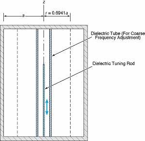
The figure illustrates how the technique could be applied to a cavity excited in the TEM020 mode. All of the modes in the TM0n0 family feature electric-field maxima along the z axis and at other radial positions that depend on the mode order (n). In the TEM020 mode, the off-z-axis maximum occurs at r/a = 0.6941, where r is the radial coordinate and a is the radius of the cylindrical cavity wall. Rods of sample material could be placed symmetrically about the z axis at r/a = 0.6941 to intercept the electric-field maximum there for maximum heating, while a dielectric rod (optionally surrounded by a narrow dielectric tube) could be placed at the z axis to intercept the electric-field maximum there for maximum tuning effect. The fine resonance frequency would be adjusted by adjusting the length of insertion of the rod. Alternatively, a sample could be placed at the z axis and tuning rods could be positioned symmetrically at r/a = 0.6941.
The position of the tuning rod could be adjusted automatically by use of a feedback control system. A sensor would provide an error signal that would be used to generate commands for a motor controller. The motor would move the rod in or out by an amount that would depend on the magnitude and sign of the difference between the actual and desired resonance frequencies. A control technique that could be adapted to this application was described in "Using Vibrations to Match Impedance of a Microwave Cavity" (NPO-19500), NASA Tech Briefs, Vol. 20, No. 10 (October 1996), page 56.
This work was done by Martin Barmatz of Caltech and Henry Jackson of ACRO Service Corp. for NASA's Jet Propulsion Laboratory.
In accordance with Public Law 96-517, the contractor has elected to retain title to this invention. Inquiries concerning rights for its commercial use should be addressed to
Technology Reporting Office
JPL
Mail Stop 122-116
4800 Oak Grove Drive
Pasadena, CA 91109
(818) 354-2240
Refer to NPO-20409
This Brief includes a Technical Support Package (TSP).

Improved tuning of a microwave cavity for heating samples
(reference NPO20409) is currently available for download from the TSP library.
Don't have an account?
Overview
The document is a technical support package from NASA detailing advancements in the tuning of microwave cavities for heating samples, specifically focusing on a method developed by Martin Barmatz of Caltech and Henry Jackson of ACRO Service Corp. for NASA's Jet Propulsion Laboratory (JPL). The work is encapsulated in the NASA Tech Brief NPO-20409, published in November 1998.
The primary objective of this research is to improve the efficiency of microwave heating by optimizing the tuning of microwave cavities. The document outlines how the insertion of dielectric materials into the cavity can affect the resonance frequency, typically lowering it. This is particularly relevant when processing materials that may change their dielectric properties upon heating. The tuning method described aims to maintain the cavity's resonance frequency within the fixed frequency band of the magnetron, which is crucial for effective heating.
One embodiment of the tuning method involves positioning the material to be processed near the maximum electric field of the cavity, specifically at a cylindrical surface defined by a certain ratio (r/a = 0.6941). The materials being processed can vary, including fibers, rods, tubes, or discrete units, and their placement along the cavity is critical for achieving optimal heating results.
The document also emphasizes the importance of angular symmetry in the cavity design, which helps mitigate detuning effects caused by the introduction of different materials. By ensuring that the cavity remains symmetrically tuned, the efficiency of microwave energy transfer can be maximized, leading to more uniform heating of the samples.
In terms of commercial application, the document notes that the contractor has retained title to the invention, and inquiries regarding rights for commercial use should be directed to the Technology Reporting Office at JPL.
Overall, this technical support package highlights significant advancements in microwave cavity tuning, which could have broad implications for various applications in materials processing and heating technologies. The research represents a step forward in enhancing the effectiveness and efficiency of microwave heating systems, potentially benefiting industries that rely on precise thermal processing.