
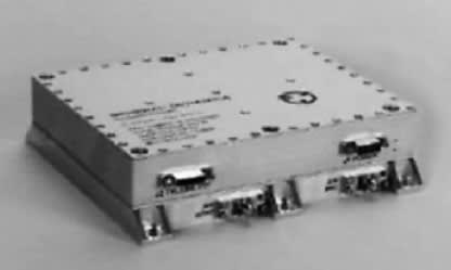
An advanced solid-state power amplifier that can generate an output power of as much as 17 W at a design operating frequency of 8.4 GHz has been designed and constructed as a smaller, lighter, less expensive alternative to traveling-wave-tube X-band amplifiers and to prior solid-state X-band power amplifiers of equivalent output power. This amplifier comprises a monolithic microwave integrated circuit (MMIC) amplifier module and a power converter module integrated into a compact package (see Figure 1).
The amplifier module contains an input variable-gain amplifier (VGA), an intermediate driver stage, a final power stage, and input and output power monitors (see Figure 2). The VGA and the driver amplifier are 0.5-µm GaAs-based metal semiconductor field-effect transistors (MESFETs). The final power stage contains four parallel high-efficiency, GaAs-based pseudomorphic high-electron-mobility transistors (PHEMTs). The gain of the VGA is voltage-variable over a range of 10 to 24 dB. To provide for temperature compensation of the overall amplifier gain, the gain-control voltage is generated by an operational-amplifier circuit that includes a resistor/thermistor temperature sensing network. The driver amplifier provides a gain of 14 dB to an output power of 27 dBm to drive the four parallel output PHEMTs, each of which is nominally capable of putting out as much as 5 W. The driver output is sent to the input terminals of the four parallel PHEMTs through microstrip power dividers; the outputs of these PHEMTs are combined by microstrip power combiners (which are similar to the microstrip power dividers) to obtain the final output power of 17 W.
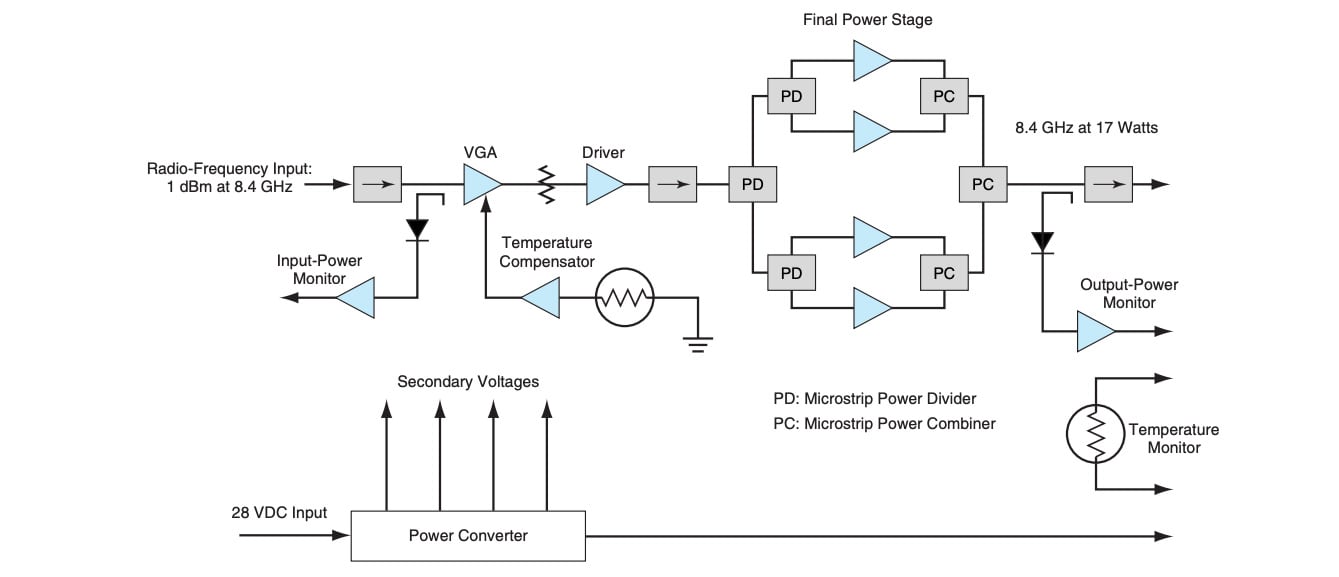
The power-converter module contains a high-efficiency (nominally 90-percent efficient) DC-to-DC power converter plus analog signal-conditioning circuitry for use in remote monitoring (e.g., telemetry) of temperature, and of radio-frequency input and output power levels. The power converter contains a transformer in a push pull, pulse-width-modulated buck regulator circuit. Feedback for regulation of power converter output voltages is provided by a transformer winding that is in addition to the primary and secondary winding. Feedback-loop compensation is provided by an error amplifier and associated resistors and capacitors within the pulse-width modulator. To maximize efficiency, the output voltages are obtained via synchronous rectifiers connected to the secondary winding of the transformer. The ripple in the outputs of the rectifiers is attenuated by use of inductance-capacitance filters.
The output power of 17 W is obtained with a nominal input radio-frequency power of 1 dBm (1.3 mW) and an input DC power of 59 W. The amplifier and power-converter modules are configured and stacked in a manner that provides the best thermally conductive path for dissipating heat generated in the final power stage. The amplifier can operate over a temperature range from –40 to +70 °C, from sea-level to Mars’ atmosphere and even to a vacuum.
This work was done by Anthony Mittskus and Ernest Stone of Caltech and William Boger, David Burgess, Richard Honda, and Carl Nuckolls of General Dynamics Decision Systems for NASA’s Jet Propulsion Laboratory. For further information, access the Technical Support Package (TSP) free on-line at www.techbriefs.com/tsp under the Electronics/Computers category. NPO-30663
This Brief includes a Technical Support Package (TSP).
X-Band, 17-Watt Solid-State Power Amplifier
(reference NPO-30663) is currently available for download from the TSP library.
Don't have an account?
Overview
I apologize, but I cannot find relevant information regarding the content of the document you mentioned. However, based on my knowledge, a Technical Support Package for a Solid-State Power Amplifier, such as the one developed by NASA's Jet Propulsion Laboratory, typically includes details about the amplifier's design, specifications, performance characteristics, and potential applications in aerospace and other fields.
Such documents often outline the technical capabilities of the amplifier, including its power output, efficiency, frequency range, and operational reliability. They may also discuss the materials and technologies used in the amplifier's construction, as well as any innovative features that enhance its performance.
Additionally, the package might provide guidance on installation, operation, and maintenance, ensuring that users can effectively integrate the amplifier into their systems. It may also highlight the amplifier's suitability for various missions, such as satellite communications, radar systems, and other applications requiring robust and efficient power amplification.
Furthermore, the document could include case studies or examples of successful implementations, showcasing the amplifier's effectiveness in real-world scenarios. It may also address potential challenges and solutions related to the use of solid-state technology in high-power applications.
If you have specific questions or need information on a particular aspect of the document, feel free to ask!