
An efficient arrangement of four switches has been conceived for coupling, to four output ports, the output powers of any subset of four devices that are members of a redundant set of five devices. In normal operation, the output power of each of four of the devices would be coupled to one of the four output ports. The remaining device would be kept as a spare: normally, its output power would be coupled to a load, wherein that power would be dissipated. In the event of failure of one of the four normally used devices, that device would be disconnected from its output port and connected to the load, and the spare device would be connected to the output from which the failed device was disconnected. Alternatively or in addition, the outputs of one or more devices could be sent to ports other than the ones originally assigned to them.
In the original intended application, the devices would be microwave amplifiers and the switches would be mechanically actuated waveguide switches. The arrangement could also be generalized to devices other than microwave amplifiers, to switches other than mechanically actuated microwave switches, and to greater numbers of switches, ports, and devices (N, N, and N + 1, respectively, where N > 4).
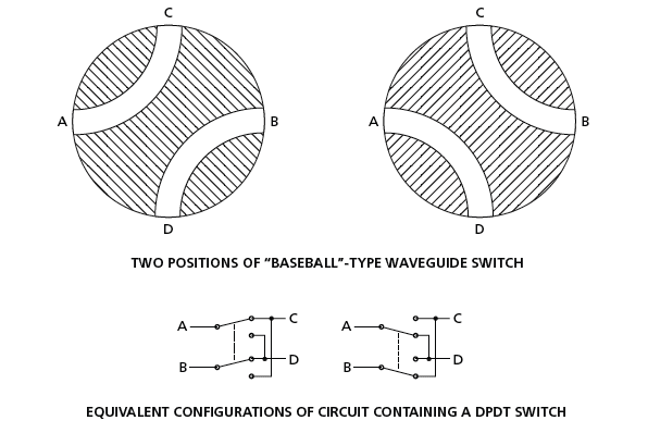
The mechanically actuated microwave switches in the original application would be two-position, four-port switches of a type known in the art as “baseball switches” because of the resemblance between their waveguide cross sections and the patterns of stitches on baseballs. Figure 1 depicts the two positions of a baseball switch and the corresponding positions of a nominally equivalent circuit containing a double-pole, double-throw (DPDT) switch.
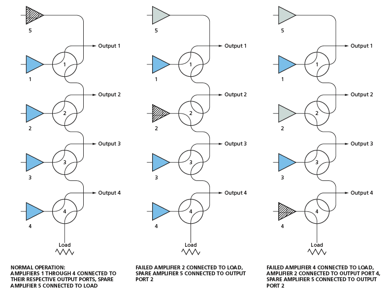
Figure 2 depicts three examples of useable switching configurations representative of the modes of operation described above. It should be apparent from casual inspection that any of those modes can be attained by actuation of one or more switches. In the original application and perhaps in other potential applications, safety considerations dictate that switching configurations be limited to those in which every amplifier is connected to either an output port or to the load; non-connection of an amplifier or connection of an amplifier to another amplifier is not allowed.
This work was done by James Lux and Robert McMaster of Caltech for NASA’s Jet Propulsion Laboratory.
This Brief includes a Technical Support Package (TSP).
Efficient Switching Arrangement for ( N + 1)/ N Redundancy
(reference NPO-41421) is currently available for download from the TSP library.
Don't have an account?
Overview
The document titled "Efficient Switching Arrangement for (N + 1)/N Redundancy," developed by NASA's Jet Propulsion Laboratory, presents a reliable system designed to ensure continuous operation of amplified outputs in critical applications. The system incorporates a fifth spare amplifier that can be activated if one of the four primary amplifiers fails, thereby maintaining functionality without interruption.
The core of the system is a switching scheme that utilizes a minimal number of switches to connect the amplifiers to the output ports. Specifically, it employs a four-port switch configuration that allows for two distinct connection setups, effectively routing signals from the amplifiers to the outputs. This design is particularly advantageous in applications requiring redundancy, as it simplifies the switching mechanism while ensuring that all amplifiers can be tested without the need for additional hardware.
The document describes two types of switch implementations: a conventional double pole double throw (DPDT) switch and a more specialized RF or microwave switch. The latter is characterized by moving leaves that either bridge contacts or do not, which is essential for high-frequency applications. The system's design is flexible, allowing for the use of various switch types, including mechanical, ferrite, and electromechanical relays, as well as potential applications in pneumatic or hydraulic systems.
An important aspect of the switching arrangement is its safety feature, which guarantees that no amplifier output can be routed to any destination other than the designated output ports or the load. This ensures that the system operates safely and reliably under all configurations.
The document also highlights the potential for this switching arrangement to be applied beyond amplifiers, suggesting its utility in switching solar panels, batteries, and other systems requiring efficient relay or solid-state switching.
Overall, the document outlines a robust and efficient approach to amplifier redundancy, emphasizing the benefits of reduced complexity, enhanced reliability, and the ability to conduct thorough testing of all components. This innovative switching arrangement represents a significant advancement in aerospace technology, with broader implications for various industries requiring reliable and efficient switching solutions.